What Is the Beam Load Calculator?
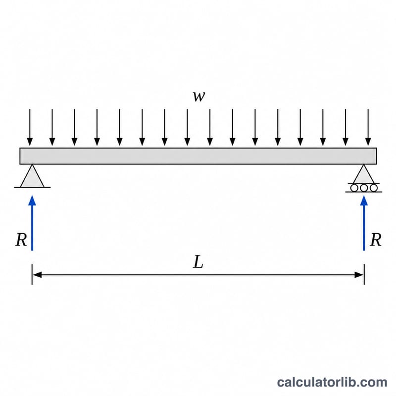
This calculator determines the structural response of a simply supported beam carrying a uniformly distributed load (UDL). Given the load intensity w (force per unit length) and the span L, it returns the maximum bending moment, the maximum shear force, the support reactions, and the total load. These values are the starting point for sizing beams in timber, steel, and concrete design.
How to Use It
Enter the distributed load w in kilonewtons per metre (kN/m) and the clear span L in metres. Press calculate to read the peak bending moment at midspan and the shear at the supports. Keep units consistent — if you use kN/m and metres, results are in kN·m and kN.
The Formula Explained
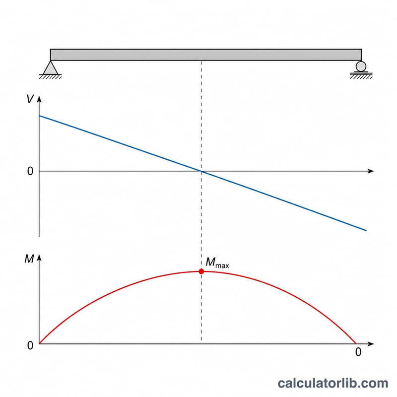
For a simply supported beam with a UDL the maximum bending moment occurs at midspan: $$M_{max} = \frac{wL^{2}}{8}$$ The maximum shear force and each support reaction occur at the ends: $$V_{max} = \frac{wL}{2}$$ The total downward load is simply \(w \times L\), split equally between the two supports.
Worked Example
Suppose a beam spans 6 m and carries a UDL of 10 kN/m. The maximum moment is $$M = \frac{10 \times 6^{2}}{8} = \frac{360}{8} = 45 \text{ kN}\cdot\text{m}$$ The total load is \(10 \times 6 = 60\) kN, so each reaction (and the max shear) is \(60 / 2 = 30\) kN.
Beam Formula Reference for Other Load & Support Cases
The calculator above handles the most common design case: a simply supported beam under a uniformly distributed load (UDL). The table below collects the closed-form expressions for several standard beam-and-load configurations so you can compare results or check a different support condition. In all formulas \(w\) is the distributed load per unit length, \(P\) is a concentrated (point) load, and \(L\) is the span between supports.
| Case | Maximum bending moment \(M_{max}\) | Maximum shear \(V_{max}\) | Support reaction(s) |
|---|---|---|---|
| Simply supported, UDL | \(\dfrac{wL^{2}}{8}\) (at midspan) | \(\dfrac{wL}{2}\) (at supports) | \(R_A = R_B = \dfrac{wL}{2}\) |
| Simply supported, central point load | \(\dfrac{PL}{4}\) (at midspan) | \(\dfrac{P}{2}\) | \(R_A = R_B = \dfrac{P}{2}\) |
| Fixed–fixed, UDL | \(\dfrac{wL^{2}}{12}\) (at supports), \(\dfrac{wL^{2}}{24}\) (at midspan) | \(\dfrac{wL}{2}\) (at supports) | \(R_A = R_B = \dfrac{wL}{2}\) |
| Cantilever, UDL | \(\dfrac{wL^{2}}{2}\) (at fixed end) | \(wL\) (at fixed end) | \(R = wL\), fixing moment \(\dfrac{wL^{2}}{2}\) |
| Cantilever, end point load | \(PL\) (at fixed end) | \(P\) (at fixed end) | \(R = P\), fixing moment \(PL\) |
Note that the fixed-end cases develop negative (hogging) moments at the supports, which for a fixed–fixed UDL are larger in magnitude than the midspan moment. The cantilever cases produce the largest moments of all for a given \(w\) and \(L\) because the load has no second support to share it.
Bending Moment & Shear Across Common Spans and Loads
The values below are for a simply supported beam carrying a uniformly distributed load. For each combination the total applied load is \(wL\), each support reaction (and the maximum shear) is \(V_{max}=\tfrac{wL}{2}\), and the maximum bending moment at midspan is \(M_{max}=\tfrac{wL^{2}}{8}\). These are unfactored characteristic values.
| \(w\) (kN/m) | \(L\) (m) | Total load \(wL\) (kN) | \(V_{max}=wL/2\) (kN) | \(M_{max}=wL^{2}/8\) (kN·m) |
|---|---|---|---|---|
| 5 | 3 | 15 | 7.5 | 5.625 |
| 5 | 6 | 30 | 15 | 22.5 |
| 5 | 9 | 45 | 22.5 | 50.625 |
| 10 | 3 | 30 | 15 | 11.25 |
| 10 | 6 | 60 | 30 | 45 |
| 10 | 9 | 90 | 45 | 101.25 |
| 20 | 3 | 60 | 30 | 22.5 |
| 20 | 6 | 120 | 60 | 90 |
| 20 | 9 | 180 | 90 | 202.5 |
Notice that the maximum moment grows with the square of the span: doubling \(L\) at constant \(w\) quadruples \(M_{max}\), while the reaction and shear only double. Span length is therefore usually the dominant driver of required beam size.
Interpreting Your Bending Moment and Shear Results
The two outputs from this calculator serve different parts of a beam design check:
- Maximum bending moment \(M_{max}\) governs the required section modulus. For a beam to remain below an allowable bending stress \(\sigma_{allow}\), the section must satisfy \(S \ge \dfrac{M_{max}}{\sigma_{allow}}\). Once \(M_{max}\) and a chosen section are known, the resulting bending stress can be checked from \(\sigma = \dfrac{M\,c}{I}\), where \(c\) is the distance from the neutral axis to the extreme fibre and \(I\) is the second moment of area.
- Maximum shear \(V_{max}\) governs shear and web checks. For a steel section this drives the web shear capacity check; for timber and concrete it drives shear-strength and reinforcement checks. The shear stress distribution \(\tau = \dfrac{VQ}{Ib}\) is highest near the neutral axis.
Several important limitations apply when using these numbers:
- The values returned are unfactored internal forces derived directly from the characteristic load you entered. Design to a limit-state code (e.g. Eurocode or AISC) requires applying the appropriate load factors and combinations before comparing demand against factored resistance.
- Self-weight of the beam itself is not included unless you added it into \(w\). It should be incorporated as part of the dead load.
- Serviceability — deflection, vibration and crack control — is a separate set of checks. A beam can be strong enough in bending and shear yet still fail a span/deflection limit, so deflection must be verified independently.
- This formula assumes an ideal simply supported beam with a uniform load, prismatic section, and material behaving elastically. Real connections, point loads, continuity, lateral-torsional buckling and load eccentricity change the result.
These calculations are provided for general engineering reference and education only and are not a substitute for professional design. A qualified, licensed engineer must verify any structural member against the governing standard for its jurisdiction and use.
FAQ
Does this include self-weight? No. Add the beam's self-weight to w if you want it accounted for.
Is this for simply supported beams only? Yes. Fixed or cantilever beams use different formulas (e.g. \(wL^{2}/12\) or \(wL^{2}/2\)).
What about deflection? This tool computes internal forces only; deflection also requires the modulus of elasticity E and second moment of area I.