What Is Bending Stress?
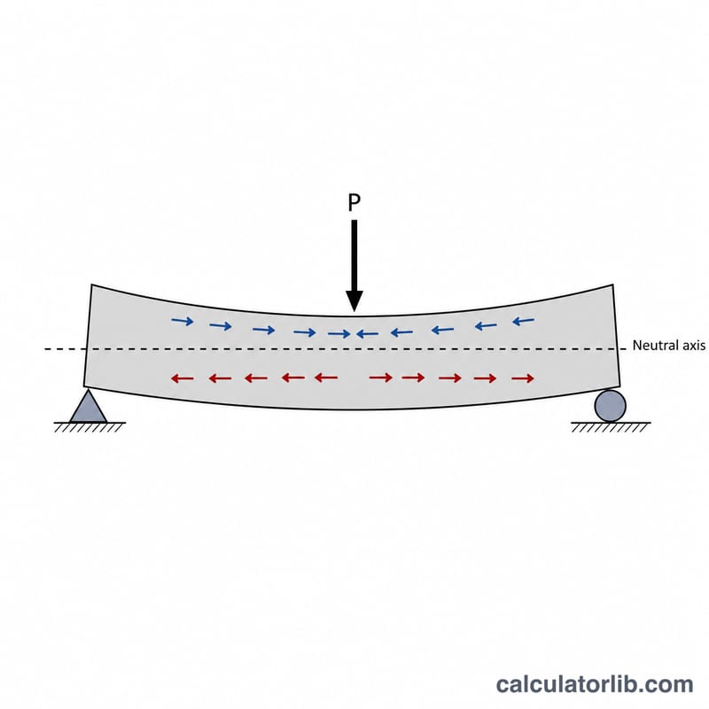
Bending stress is the internal stress induced in a structural member, such as a beam, when it is subjected to a bending moment. It describes how much tension or compression the material experiences at a given point across the cross-section. This calculator uses the classic flexure formula \(\sigma = M\cdot c/I\) to determine the maximum bending stress at the outermost fiber of a loaded beam. It is a universal engineering tool applicable anywhere, provided you use consistent SI units.
How to Use This Calculator
Enter three values: the bending moment \(M\) in newton-metres (\(\text{N}\cdot\text{m}\)), the distance \(c\) from the neutral axis to the outermost fiber in metres (m), and the moment of inertia \(I\) (second moment of area) in metres to the fourth power (m⁴). The calculator returns the bending stress in both pascals (Pa = N/m²) and megapascals (MPa = N/mm²), which is the unit most often used to compare against material yield strength.
The Formula Explained
The flexure formula $$\sigma = \frac{\text{Moment }M \cdot \text{Distance }c}{\text{Inertia }I}$$ comes from beam bending theory. A larger bending moment or a fiber farther from the neutral axis increases stress, while a larger moment of inertia (a stiffer, deeper cross-section) reduces it. The ratio \(I/c\) is often called the section modulus, \(S\), so the formula can also be written \(\sigma = M/S\).
Worked Example
Suppose a beam carries a bending moment of \(M = 1000\ \text{N}\cdot\text{m}\), the outer fiber is \(c = 0.05\ \text{m}\) from the neutral axis, and the moment of inertia is \(I = 0.0000208\ \text{m}^4\). Then $$\sigma = \frac{1000 \times 0.05}{0.0000208} \approx 2{,}403{,}846\ \text{Pa} \approx 2.4\ \text{MPa}.$$
Typical Yield Strengths of Common Materials
To judge whether a calculated bending stress is acceptable, compare it against the material's strength. The values below are representative, nominal figures for engineering comparison; always use the certified properties of the specific grade and product form in design.
| Material | Approx. yield strength (MPa) | Notes |
|---|---|---|
| Structural steel ASTM A36 | ~250 | Common mild structural steel |
| High-strength low-alloy steel (A572 Gr. 50) | ~345 | Higher strength structural grade |
| Quenched & tempered alloy steel (A514) | ~690 | High-strength plate |
| Aluminium 6061-T6 | ~276 | Yield (0.2% offset) |
| Gray cast iron | ~ (brittle) — tensile strength ~150–250 | No distinct yield; design on ultimate/fracture |
| Structural timber (softwood, bending) | ~10–50 (allowable bending varies by species/grade) | Highly grade-dependent |
| Concrete | Compressive ~20–40; tensile ~2–5 | Weak in tension/bending; usually reinforced |
Brittle materials such as gray cast iron and concrete do not exhibit a clear yield point, so their bending capacity is governed by tensile fracture strength rather than yield. Concrete is rarely used in bending without steel reinforcement because its tensile strength is so low.
Interpreting Your Bending Stress Result
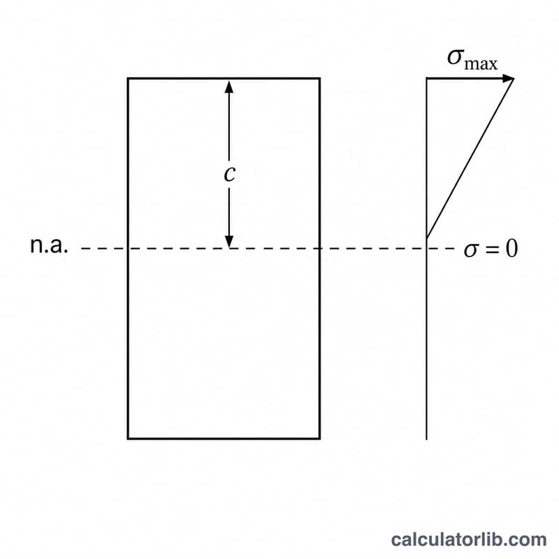
The value \(\sigma\) returned by \(\sigma = M\,c/I\) is the maximum bending stress at the extreme fiber — the point farthest from the neutral axis (distance \(c\)). It is the largest normal stress due to bending in that cross-section; stress varies linearly from zero at the neutral axis to this peak value at the surface. This is the number that matters for checking the section.
For the design to be safe, this stress must stay below the material's allowable stress, which is the yield strength (or, for brittle materials, the fracture strength) divided by a factor of safety:
$$\sigma_{\text{allow}} = \frac{\sigma_{\text{yield}}}{\text{FoS}}, \qquad \text{FoS} = \frac{\sigma_{\text{yield}}}{\sigma_{\text{actual}}}$$The factor of safety (FoS) expresses how much margin exists between the stress the part actually carries and the stress at which it begins to fail. For example, if a steel beam (A36, \(\sigma_{\text{yield}} \approx 250\text{ MPa}\)) carries a calculated bending stress of \(\sigma_{\text{actual}} = 100\text{ MPa}\), then \(\text{FoS} = 250 / 100 = \)2.5. Typical design factors range from about 1.5 to 4 or more depending on the loading, consequences of failure, and code requirements.
If \(\sigma\) reaches the yield strength, the material begins to deform permanently (plastically) — the beam will not fully return to its original shape after the load is removed. Beyond that, continued loading risks gross deformation and ultimately fracture. A bending stress below the allowable value with an adequate FoS keeps the beam in the elastic range, which is the intended operating condition per established mechanics-of-materials principles. Use \(\sigma = M\,c/I\) only within its assumptions: prismatic, homogeneous, linearly elastic beams in pure bending about a principal axis.
This is general engineering information, not a substitute for analysis and review by a qualified professional engineer for your specific application.
FAQ
What is c? It is the perpendicular distance from the neutral axis to the most extreme fiber; for a symmetric section this equals half the section depth.
How do I find I? For a rectangle of width \(b\) and height \(h\), \(I = b\cdot h^3/12\). Other shapes have standard formulas or tabulated values.
Is the result tension or compression? The magnitude is the same on both faces — one side is in tension and the opposite side is in compression.