What Is a Bridge Rectifier Calculator?
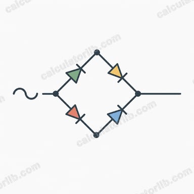
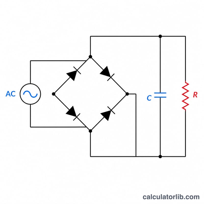
A bridge rectifier uses four diodes to convert AC into pulsating DC, conducting on both halves of the AC waveform (full-wave rectification). This calculator estimates the average DC output voltage and the ripple voltage you can expect after a smoothing capacitor, given the peak input voltage, the diode forward drop, the load current, the line frequency, and the filter capacitor value.
How to Use It
Enter the peak (not RMS) voltage of the AC waveform reaching the bridge. If you only know the RMS value, multiply it by 1.414. Set the diode drop per diode (typically 0.7 V for silicon, ~0.3 V for Schottky), the expected load current in amps, your mains frequency (50 or 60 Hz), and the filter capacitor in microfarads. The tool returns the average DC output, the peak DC voltage after the two conducting diode drops, and the peak-to-peak ripple.
The Formula Explained
The average value of a full-wave rectified sine is 2·Vpeak/π ≈ 0.637·Vpeak. Because two diodes conduct at any instant in a bridge, we subtract 2·Vdiode. Ripple uses Vripple = Iload / (2·f·C); the factor of 2 reflects that a full-wave rectifier charges the capacitor twice per cycle.
Worked Example
With Vpeak = 17 V, Vdiode = 0.7 V: Vdc = (2 × 17)/π − 1.4 = 10.823 − 1.4 ≈ 9.42 V. For Iload = 1 A, f = 50 Hz, C = 1000 µF: Vripple = 1 / (2 × 50 × 0.001) = 10 V peak-to-peak — a clear sign you'd want a much larger capacitor.
Constants & Reference Values
A full-wave bridge rectifier uses four diodes so that both halves of the AC sine wave drive current through the load in the same direction. The conduction path always passes through two diodes in series, so two forward voltage drops are subtracted from the peak. The values below are the constants and reference figures used in the calculations.
| Quantity | Symbol / Value | Notes |
|---|---|---|
| Average factor (full-wave sine) | 2/π ≈ 0.637 | Mean value of a full-wave rectified sine relative to its peak |
| RMS-to-peak factor | √2 ≈ 1.414 | \(V_{peak} = \sqrt{2}\,V_{rms}\) |
| Silicon diode drop | ~0.7 V | Typical forward voltage of a standard rectifier diode (e.g. 1N400x) |
| Schottky diode drop | ~0.3 V | Lower drop, less heat, good for low-voltage supplies |
| Germanium diode drop | ~0.3 V | Older technology, low forward voltage |
| Ripple frequency | 2 × line frequency | 100 Hz for 50 Hz mains, 120 Hz for 60 Hz mains |
Variable Units
| Field | Variable | Unit |
|---|---|---|
| vpeak | Peak input voltage \(V_{peak}\) | volts (V) |
| vdiode | Diode forward drop \(V_{diode}\) | volts (V) |
| iload | Load current \(I_{load}\) | amperes (A) |
| freq | Line frequency \(f\) | hertz (Hz) |
| cap | Filter capacitor \(C\) | farads (F); often entered in microfarads (µF) |
The average DC output (no filter capacitor) is \(V_{DC} = \frac{2 V_{peak}}{\pi} - 2 V_{diode}\). With a filter capacitor the output rises toward the peak minus two diode drops, and the peak-to-peak ripple is estimated by \(V_{r(pp)} = \frac{I_{load}}{2 f C}\), where \(2f\) is the ripple frequency.
Interpreting Your Result
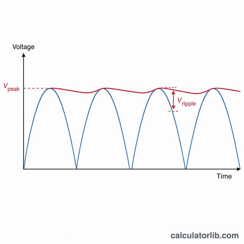
Average DC vs peak DC. Without a filter capacitor, the output is a series of half-sine humps whose average value is \(\frac{2 V_{peak}}{\pi} - 2 V_{diode} \approx 0.637\,V_{peak}\) minus the two diode drops. Once a filter capacitor is added, the capacitor holds the output near the peak value, \(V_{peak} - 2 V_{diode}\), and the meaningful figure becomes that peak level with a ripple riding on top.
What ripple p-p means. The peak-to-peak ripple is how far the voltage sags between charging pulses before the next pulse tops it back up. Expressed as a percentage, ripple % = \(\frac{V_{r(pp)}}{V_{DC}} \times 100\). For example, 1.0 V of ripple on a 15.6 V output is about 6.4 %. Linear regulators downstream can tolerate moderate ripple as long as the trough stays above the regulator's dropout voltage, but sensitive analog circuits want ripple well under 1 %.
Lower ripple needs more C or more f. Because \(V_{r(pp)} = \frac{I_{load}}{2 f C}\), you reduce ripple by increasing the filter capacitance or by working at a higher ripple frequency (a 60 Hz supply ripples at 120 Hz and so ripples about 17 % less than a 50 Hz supply for the same capacitor). You cannot reduce ripple by lowering load current unless your load actually draws less.
A warning sign. If the calculator reports a ripple of several volts, the capacitor is undersized for the current being drawn — the output trough may dip too low for a regulator to maintain its target, causing hum or instability. Increase C until the ripple is a small fraction of the DC output.
Approximation note. These results assume ideal diodes with a fixed forward drop, a light-to-moderate load relative to the transformer's capability, and the simple linear-discharge ripple model. Real supplies have transformer winding resistance, diode dynamic resistance, and capacitor ESR that all increase voltage drop and alter ripple shape, so treat the figures as design estimates rather than exact values.
FAQ
Why use 2f for ripple? A bridge rectifier produces two pulses per AC cycle, so the capacitor recharges twice as often as a half-wave circuit, halving the ripple.
Should I use peak or RMS voltage? Use peak. The bridge sees the instantaneous peak. RMS × 1.414 = peak for a sine wave.
Why subtract two diode drops? In a full-wave bridge, current always flows through two diodes in series, so the output is reduced by both their forward voltages.