What is a Buck Converter Calculator?
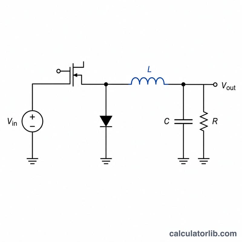
A buck converter is a switching DC-DC regulator that steps a higher input voltage down to a lower, regulated output voltage with high efficiency. This calculator finds the steady-state output voltage from the input voltage and switching duty cycle, and additionally sizes the inductor for a chosen ripple current. The formulas apply to a converter operating in continuous conduction mode (CCM).
How to use it
Enter the input voltage (Vin), the switch duty cycle (D) as a percentage, the switching frequency in kHz, the output load current, and your target inductor ripple current as a percentage of the output current (30% is a common starting point). The calculator returns the regulated output voltage, the inductor ripple current in amps, and a recommended inductance value in microhenries.
The formula explained
For an ideal buck converter in CCM the conversion ratio is simply Vout = Vin × D, where D is the fraction of each switching cycle that the high-side switch is on. The inductor value follows from the volt-second balance: L = (Vin − Vout) · D / (f · ΔI_L), where f is the switching frequency in hertz and ΔI_L is the desired peak-to-peak inductor ripple current.
Worked example
Step 12 V down with D = 42% (0.42): Vout = 12 × 0.42 = 5.04 V. With Iout = 2 A and 30% ripple, ΔI_L = 0.6 A. At f = 100 kHz, L = (12 − 5.04) × 0.42 / (100000 × 0.6) = 2.9232 / 60000 ≈ 48.72 µH.
Key Terms & Variables
A buck converter is a switch-mode DC-DC circuit that steps a higher input voltage down to a lower, regulated output. The variables below appear in the converter's defining equations.
- Input voltage (Vin)
- The unregulated DC voltage supplied to the converter, in volts (V). It must always be higher than the desired output for a buck topology to operate.
- Output voltage (Vout)
- The regulated DC voltage delivered to the load, in volts (V). In an ideal continuous-conduction buck converter \(V_{out} = V_{in} \times D\).
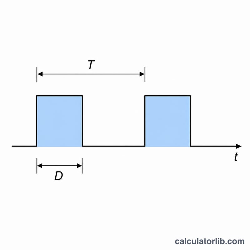
- Duty cycle (D)
- The fraction of each switching period during which the high-side switch is on, expressed as a ratio (0–1) or percent (0–100%). It directly sets the conversion ratio: \(D = V_{out}/V_{in}\).
- Switching frequency (f)
- The rate at which the main switch turns on and off, in hertz (Hz) — commonly stated in kHz. Higher \(f\) allows smaller inductors and capacitors but increases switching losses.
- Inductor ripple current (\(\Delta I_L\))
- The peak-to-peak variation of current in the inductor over one switching cycle, in amperes (A). It is usually specified as a percentage of the output (load) current.
- Continuous conduction mode (CCM)
- An operating mode in which the inductor current never falls to zero during a switching cycle. The simple relation \(V_{out}=V_{in}\,D\) holds in CCM; at light loads the converter may enter discontinuous conduction mode (DCM), where the ratio also depends on load.
- Inductance (L)
- The value of the power inductor, in henries (H) — typically expressed in microhenries (µH). It sets the ripple current for a given input/output and frequency: \(L = \dfrac{(V_{in}-V_{out})\,D}{f \cdot \Delta I_L}\).
FAQ
Is the output always Vin × D? This ideal relation holds in continuous conduction mode and ignores switch/diode drops and resistive losses, which slightly lower the real output.
What ripple current should I pick? 20–40% of the maximum output current is typical; lower ripple needs a larger inductor.
Does frequency change the output voltage? No — Vout depends only on Vin and duty cycle. Frequency affects inductor and capacitor sizing, not the regulated voltage.