What is a Boost Converter Calculator?
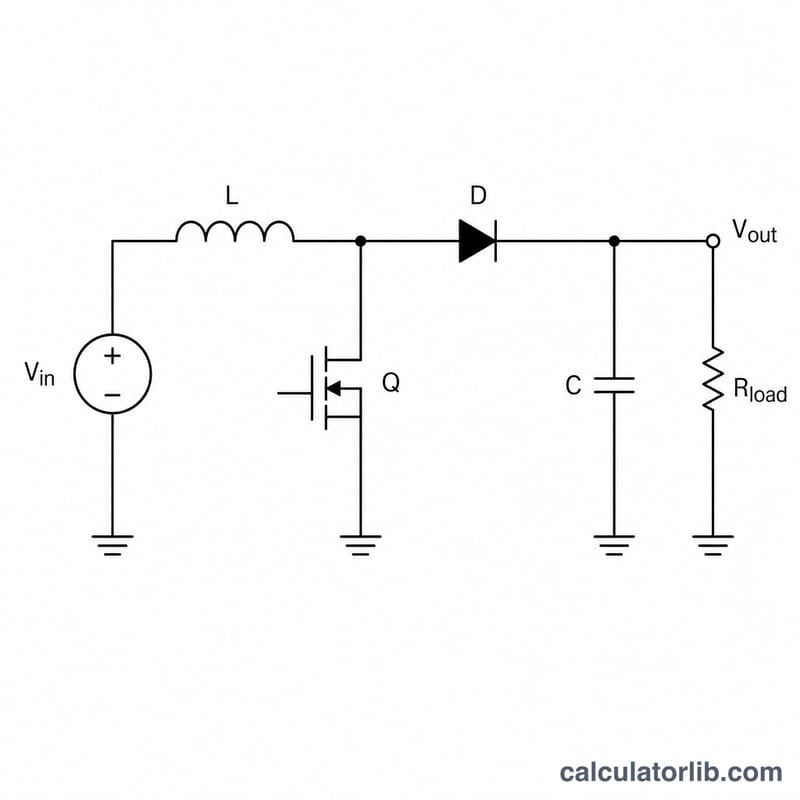
A boost converter is a switched-mode DC-DC power supply that steps a lower input voltage up to a higher output voltage. This calculator uses the ideal continuous-conduction-mode (CCM) relationship to find the output voltage from your input voltage and the switch duty cycle. It is a universal electronics tool useful for designing battery-powered devices, LED drivers, and power supplies.
How to Use It
Enter your input voltage (Vin) in volts and the duty cycle (D) as a percentage between 0 and 99%. The calculator returns the ideal output voltage and the voltage gain. Because the formula divides by (1 − D), a duty cycle of 100% is undefined (infinite gain), so keep D below 100%.
The Formula Explained
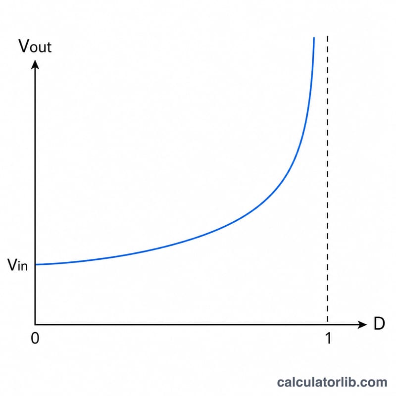
The ideal boost converter follows Vout = Vin / (1 − D), where D is the fraction of each switching cycle that the main switch is closed. When the switch is on, the inductor stores energy; when it opens, that energy is released to the output in series with the input, producing a voltage higher than Vin. As D approaches 1, the gain rises steeply. Real converters fall short of this ideal due to switch, diode, and inductor losses.
Worked Example
Suppose Vin = 5 V and D = 60% (0.60). Then Vout = 5 / (1 − 0.60) = 5 / 0.40 = 12.5 V, a voltage gain of 2.5×. So a 5 V source boosted at 60% duty cycle delivers about 12.5 V.
Interpreting Your Result
The number this calculator returns is the ideal output voltage ceiling assuming a lossless converter operating in continuous conduction mode (CCM). Use it as a design starting point, not an exact prediction of bench results.
- Real output is lower than ideal. Switch resistance, diode drop, inductor copper loss, and ESR all consume energy. Multiply the ideal figure by a typical converter efficiency of roughly 0.80 to 0.95 to estimate the realistic output. For example, an ideal 30 V at 88% efficiency yields closer to \(30 \times 0.88 \approx 26.4\,\text{V}\), so practical designs run a slightly higher duty cycle (with closed-loop regulation) to compensate.
- Very high duty cycles are fragile. As \(D\) approaches 1, the denominator \(1-D\) shrinks toward zero and the theoretical gain explodes. In practice, duty cycles above about 0.8 become inefficient and unstable: peak currents, conduction losses, and sensitivity to component tolerances all rise sharply. If your application needs a gain beyond roughly 4–5×, consider a different topology (e.g. a flyback or a cascaded/two-stage approach).
- Gain is always \(\ge 1\). Because \(0 \le D < 1\), the factor \(1/(1-D)\) is never less than one. A boost converter can only step voltage up (or pass it through at \(D = 0\)); it cannot produce an output below its input. If you need a lower output, use a buck converter instead.
This is general engineering information; always validate against your specific component datasheets, thermal limits, and control-loop design before committing to hardware.
FAQ
Why can't the duty cycle be 100%? At D = 1 the denominator (1 − D) becomes zero, giving theoretically infinite voltage — physically impossible and dangerous. Practical designs keep D well below 1.
Does this account for losses? No. This is the ideal CCM equation. Real output is lower; expect efficiency of roughly 80–95% depending on the design.
Can a boost converter lower voltage? No — a boost only steps voltage up (gain ≥ 1). Use a buck converter to step down.