What Is a Flyback Converter Calculator?
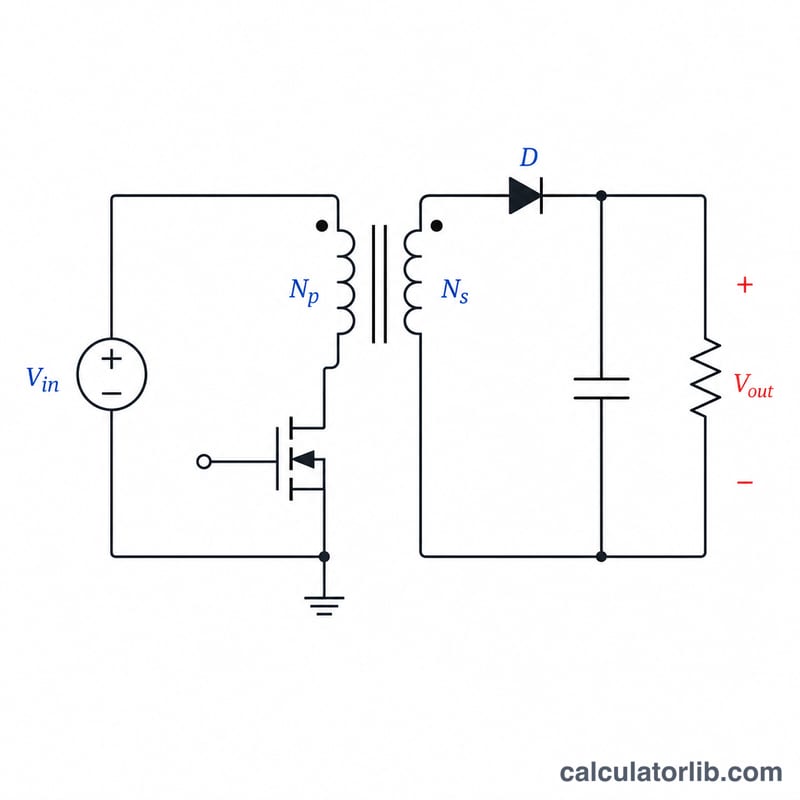
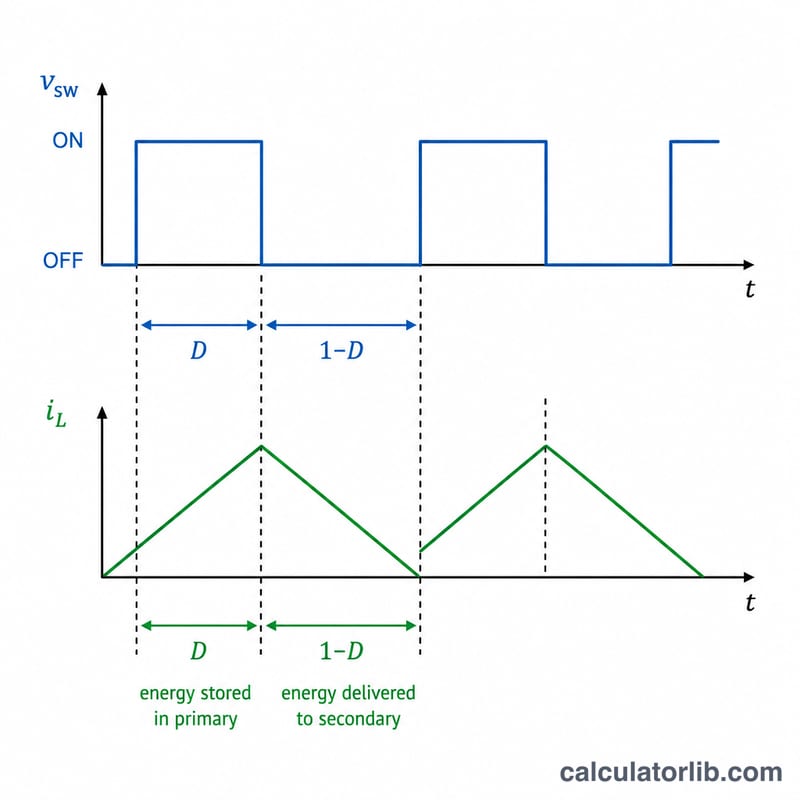
A flyback converter is an isolated DC–DC switching topology that stores energy in a coupled inductor (transformer) during the switch on-time and delivers it to the output during the off-time. This calculator estimates the steady-state output voltage in continuous conduction mode (CCM) from three parameters: the input voltage, the transformer turns ratio, and the switching duty cycle.
How to Use It
Enter the input voltage Vin, the duty cycle D (a value between 0 and 1, where 0.4 means the switch is on 40% of each cycle), and the transformer's primary and secondary turns (Np and Ns). The calculator returns the ideal output voltage along with the turns ratio and the duty term for clarity.
The Formula Explained
The governing equation is:
$$V_{out} = \text{Vin} \cdot \frac{\text{Ns}}{\text{Np}} \cdot \frac{\text{D}}{1 - \text{D}}$$
The term \(\frac{\text{Ns}}{\text{Np}}\) scales the reflected voltage by the transformer windings, while \(\frac{\text{D}}{1-\text{D}}\) captures the volt-second balance across the magnetizing inductance in CCM. As \(D\) approaches 1, the output voltage rises steeply, which is why practical designs keep \(D\) well below the maximum.
Worked Example
Suppose Vin = 12 V, D = 0.4, Np = 10, Ns = 5. The turns ratio is \(5/10 = 0.5\). The duty term is \(0.4/(1-0.4) = 0.4/0.6 = 0.6667\). Therefore $$V_{out} = 12 \times 0.5 \times 0.6667 = 4 \text{ V}.$$
FAQ
Does this account for losses? No — this is the ideal CCM relationship. Real converters lose voltage to diode drops, winding resistance, and leakage inductance, so measured output is slightly lower.
What duty cycle should I use? Most flyback designs operate between 0.3 and 0.5 at nominal input to leave headroom and limit transformer reset stress.
Is this valid in DCM? The \(\frac{\text{D}}{1-\text{D}}\) form applies to continuous conduction mode. Discontinuous conduction mode (DCM) has a load-dependent transfer function and requires a different equation.