What Is a Pi Attenuator?
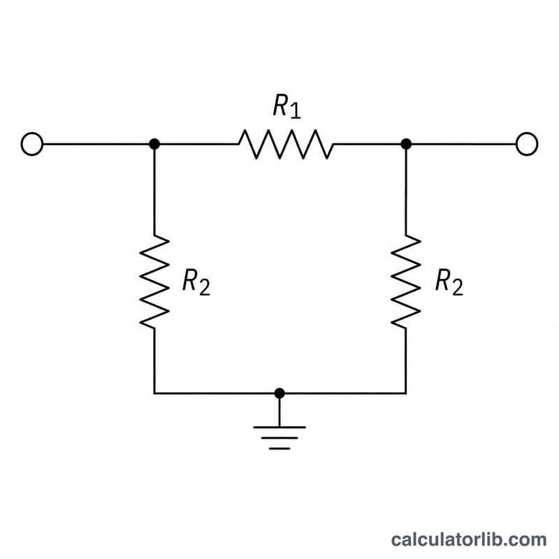
A Pi (π) attenuator is a passive resistive network shaped like the Greek letter π: two equal shunt resistors (R2) to ground on each side and one series resistor (R1) between them. It reduces signal power by a precise amount while keeping the source and load impedances matched, which is essential in RF, audio, and test-equipment design where reflections must be avoided.
How to Use This Calculator
Enter the desired attenuation in decibels (dB) and the system characteristic impedance Z (commonly 50 Ω for RF or 75 Ω for video). The calculator returns the single series resistor R1 and the value for each of the two shunt resistors R2, along with the voltage ratio K.
The Formula Explained
First convert attenuation to a linear voltage ratio: \(K = 10^{\frac{\text{dB}}{20}}\). Then the resistor values for a symmetric (equal-impedance) Pi pad are
$$R_1 = \text{Z} \cdot \frac{K+1}{K-1} \qquad R_2 = \text{Z} \cdot \frac{K^2-1}{2K}$$K must be greater than 1 (attenuation above 0 dB), otherwise R1 would be undefined.
Worked Example
For 10 dB of attenuation in a 50 Ω system:
$$K = 10^{\frac{10}{20}} = 10^{0.5} \approx 3.1623$$$$R_1 = 50 \cdot \frac{3.1623+1}{3.1623-1} = 50 \cdot \frac{4.1623}{2.1623} \approx 96.25\ \Omega$$$$R_2 = 50 \cdot \frac{10-1}{2 \cdot 3.1623} = \frac{450}{6.3246} \approx 71.15\ \Omega$$Use the nearest standard resistor values when building the pad.
FAQ
What is the difference between Pi and T attenuators? Both achieve the same attenuation; a T pad uses series-shunt-series, a Pi pad uses shunt-series-shunt. Choose based on layout and parasitic preferences.
Why two R2 resistors? The Pi network is symmetric, so each side has its own shunt resistor of equal value to maintain matching in both directions.
Can I use it for power attenuation? Yes, but verify each resistor's power rating; the input-side shunt and series resistors dissipate the most power.