What is the 555 Timer Calculator?
The 555 timer is one of the most popular integrated circuits ever made, used in oscillators, timers, pulse generators and PWM circuits. This calculator covers its astable (free-running) mode, where the chip continuously toggles its output between HIGH and LOW. Given two timing resistors (R1, R2) and a timing capacitor (C), it returns the oscillation frequency, the period, the HIGH and LOW times, and the duty cycle.
How to use it
Enter R1 and R2 in ohms (use 1000 for 1 kΩ, 10000 for 10 kΩ) and the capacitor value in microfarads (µF). Press calculate to see the resulting square-wave frequency. To get a frequency in kHz simply divide the Hz result by 1000.
The formula explained
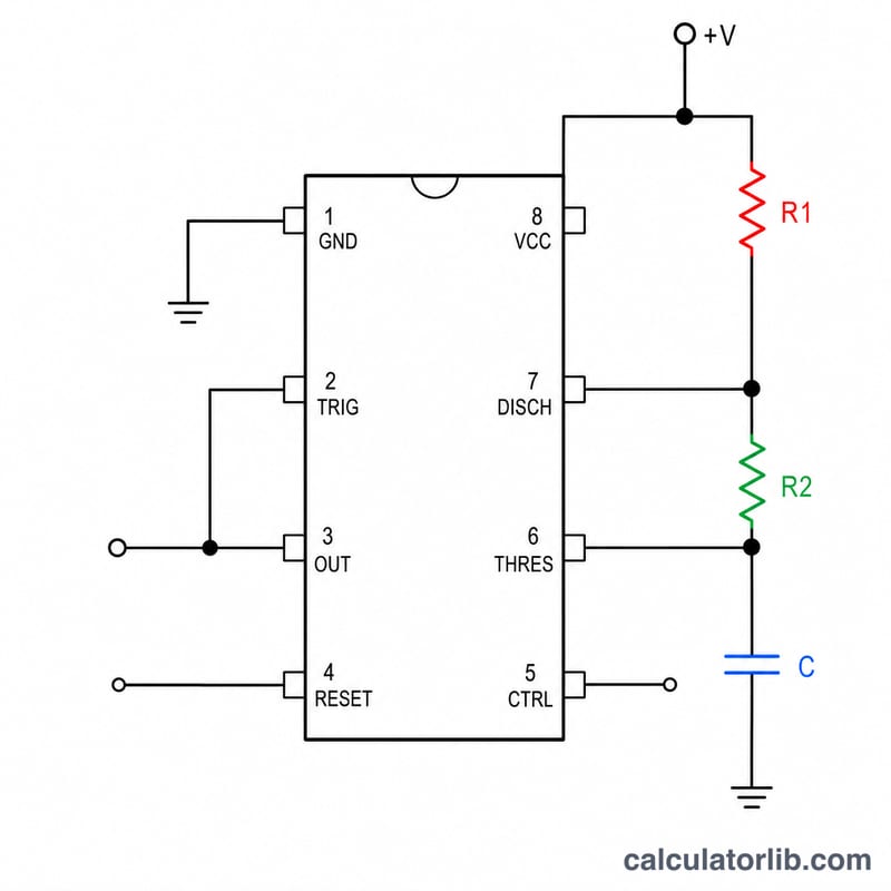
In astable mode the capacitor charges through R1 + R2 and discharges through R2 only. This gives:
$$f = \frac{1.44}{(R_1 + 2R_2)\,C}$$
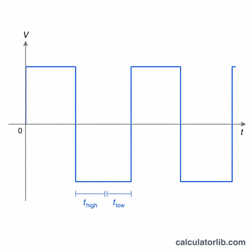
The time the output stays HIGH is \(t_H = 0.693\cdot(R_1+R_2)\cdot C\) and the time LOW is \(t_L = 0.693\cdot R_2\cdot C\). The duty cycle is \(D = \frac{R_1+R_2}{R_1+2R_2}\). Because R1 is always in the charge path but not the discharge path, the standard 555 astable duty cycle is always greater than 50%.
Worked example
With R1 = 1 kΩ (1000 Ω), R2 = 10 kΩ (10000 Ω) and C = 1 µF (\(1\times10^{-6}\) F): the denominator is \((1000 + 20000)\cdot 1\times10^{-6} = 0.021\). So $$f = \frac{1.44}{0.021} \approx 68.57\ \text{Hz},$$ with a duty cycle of \(\frac{11000}{21000} \approx 52.4\%\).
Constants & Fixed Values Used
The numeric constants in the 555 astable equations come directly from the exponential charge/discharge of the timing capacitor between the \(\tfrac{1}{3}V_{CC}\) and \(\tfrac{2}{3}V_{CC}\) comparator thresholds.
| Symbol / Value | Meaning | Origin |
|---|---|---|
| 0.693 | Coefficient for \(t_H\) and \(t_L\) | \(\ln 2 \approx 0.6931\); the capacitor crosses one comparator threshold per time constant interval of \(\ln 2\,RC\) |
| 1.44 | Numerator in the frequency formula | \(\dfrac{1}{\ln 2}\) split across charge + discharge, i.e. \(\dfrac{1}{0.693(R_1+2R_2)C}\approx\dfrac{1.44}{(R_1+2R_2)C}\) |
| Ω (ohm) | Resistance unit for R1, R2 | Enter raw ohms (1 kΩ = 1000, 1 MΩ = 1 000 000) |
| F (farad) | Capacitance unit | SI base unit used inside the formula |
| µF → F | Capacitor input scaling | \(1\ \mu F = 1\times10^{-6}\ F\); the entered µF value is multiplied by \(10^{-6}\) |
| Hz | Frequency unit | Cycles per second; \(1\text{ kHz}=1000\text{ Hz}\) |
The constant 1.44 is simply twice the reciprocal-handling of \(\ln 2\): since \(0.693 \times 2 = 1.386\) and \(1/1.386 \approx 0.721\), the commonly published shortcut \(f = 1.44/[(R_1+2R_2)C]\) is the standard datasheet rounding.
Key Terms & Variables
- Astable mode
- A free-running 555 configuration with no stable output state — it continuously oscillates between high and low, generating a repeating square-wave clock without any external trigger.
- R1
- The resistor connected between \(V_{CC}\) and the discharge/threshold node. Current flows through \(R_1\) and \(R_2\) while the capacitor charges, so \(R_1\) affects only the high time.
- R2
- The resistor between the discharge pin and the threshold/trigger node. The capacitor discharges through \(R_2\) alone, so \(R_2\) influences both high and low times.
- Timing capacitor C
- The capacitor that charges and discharges between \(\tfrac{1}{3}V_{CC}\) and \(\tfrac{2}{3}V_{CC}\). Its value sets the overall time scale of the oscillation; entered here in microfarads (µF).
- Frequency f
- How many complete output cycles occur per second, in hertz (Hz): \(f = 1.44/[(R_1+2R_2)C]\).
- Period T
- The duration of one full cycle, \(T = 1/f = t_H + t_L\), measured in seconds (or ms/µs).
- Duty cycle D
- The fraction of each period the output is high, \(D = (R_1+R_2)/(R_1+2R_2)\). For the standard two-resistor astable it always exceeds 50%.
- High time \(t_H\)
- The time the output stays high during one cycle: \(t_H = 0.693\,(R_1+R_2)\,C\).
- Low time \(t_L\)
- The time the output stays low during one cycle: \(t_L = 0.693\,R_2\,C\).
- Square wave
- The rectangular output waveform produced at pin 3, alternating between near-\(V_{CC}\) and near-ground. A perfectly symmetric square wave has a 50% duty cycle, which the basic 555 astable cannot quite reach without a diode trick.
FAQ
Why can't I get exactly 50% duty cycle? The classic astable circuit charges through R1+R2 but discharges through R2, so duty always exceeds 50%. Add a diode across R2 or use a different topology for a true 50%.
What capacitor unit should I use? Enter the value in microfarads (µF). The calculator converts it to farads internally.
Does the supply voltage matter? No. The 555's thresholds are set as fractions of the supply, so the astable frequency is independent of supply voltage.