What Is a Speaker Crossover Calculator?
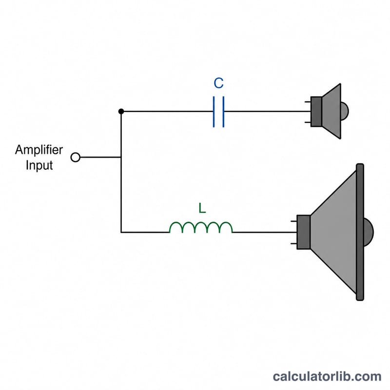
A passive crossover splits an audio signal so the right frequencies reach each driver — bass to the woofer, treble to the tweeter. This calculator designs a first-order (6 dB/octave) crossover, the simplest type, using a single series capacitor for the high-pass (tweeter) side and a single series inductor for the low-pass (woofer) side. Enter your driver impedance and desired crossover frequency to get the exact component values.
How to Use It
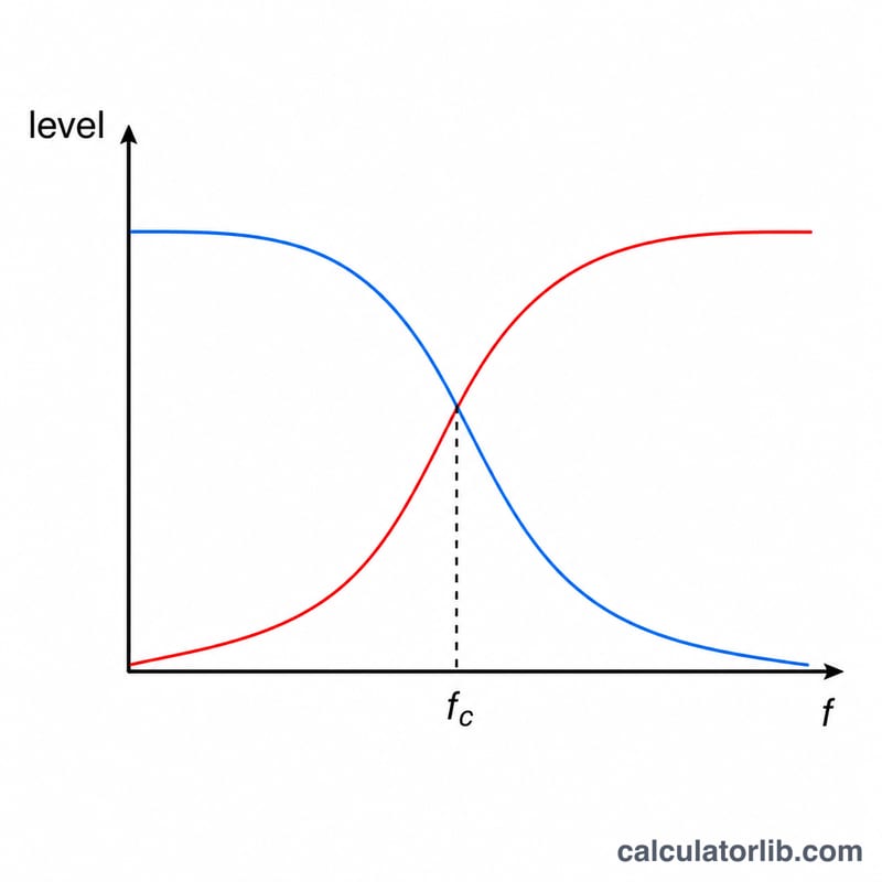
Enter the speaker (driver) impedance in ohms — typically 4 Ω, 6 Ω, or 8 Ω, printed on the driver. Then enter the crossover frequency in hertz, the point where the signal hands off between drivers (commonly 2,000–3,500 Hz for a woofer-to-tweeter split). The calculator returns the capacitor value in microfarads (µF) and the inductor value in millihenries (mH).
The Formula Explained
A first-order filter reaches the crossover point at the −3 dB level when the reactance of the component equals the load impedance. Setting capacitive reactance equal to R gives $$C = \frac{1}{2\pi R f_c}$$, and setting inductive reactance equal to R gives $$L = \frac{R}{2\pi f_c}$$. Larger impedance or higher frequency means a smaller capacitor; larger impedance or lower frequency means a larger inductor.
Worked Example
For an 8 Ω driver crossing over at 2,000 Hz: $$C = \frac{1}{2\pi \times 8 \times 2000} = \frac{1}{100{,}531} \approx 9.947\ \mu\text{F}$$ and $$L = \frac{8}{2\pi \times 2000} = \frac{8}{12{,}566} \approx 0.637\ \text{mH}$$ So you'd use roughly a 10 µF capacitor on the tweeter and a 0.64 mH inductor on the woofer.
FAQ
What does first-order mean? It uses one component per filter and rolls off at 6 dB per octave — a gentle slope with minimal phase shift, but limited driver protection.
Which capacitor and inductor should I buy? Use non-polarized (film or bipolar electrolytic) capacitors and air-core inductors rated for your power. Round to the nearest standard value.
Does this work for subwoofers? Yes, the same formula applies, but for steeper protection many builders prefer second- or fourth-order filters.