What is the AC Wattage Calculator?
This calculator finds the real power (in watts) consumed by a single-phase alternating-current load. In AC circuits, voltage and current are not always in phase, so the actual power delivered is the product of voltage, current and the power factor — the cosine of the phase angle between them. This tool is universal and works with any standard AC supply (120 V, 230 V, 240 V, etc.).
How to use it
Enter the supply voltage in volts, the current drawn in amperes, and the power factor (a number between 0 and 1). A purely resistive load like a heater has a power factor of 1; motors and electronics typically range from 0.7 to 0.95. The calculator returns the real power in watts and the apparent power in volt-amperes (VA).
The formula explained
The core equation is $$P = V \times I \times \cos\varphi$$ where P is real power (W), V is RMS voltage, I is RMS current, and \(\cos\varphi\) is the power factor. Apparent power is simply \(S = V \times I\) (in VA). Real power is what your appliance actually converts to useful work and what your energy meter bills you for.
Worked example
Suppose a motor runs on 230 V drawing 5 A with a power factor of 0.9. Real power = $$230 \times 5 \times 0.9 = 1035\ \text{W}$$ The apparent power is \(230 \times 5 = 1150\ \text{VA}\), showing the supply must be sized for more than the useful wattage.
Typical Power Factor Values by Load Type
Power factor (\(\cos\varphi\)) describes how effectively a load converts the supplied current into useful real power. Purely resistive loads have a power factor of 1.0, while motors and electronic loads draw additional reactive current that lowers the figure. The values below are typical operating ranges; the exact figure varies with load, age and design.
| Load type | Typical power factor | Notes |
|---|---|---|
| Incandescent lamp / heater (resistive) | 1.0 | Purely resistive — watts equal volt-amperes. |
| LED lighting (with driver) | 0.5 – 0.95 | Quality drivers reach 0.9+; cheap units can be low. |
| Fluorescent lamp with magnetic ballast | 0.5 – 0.6 | Improves to ~0.95 with electronic ballast or correction. |
| Refrigerator / fridge-freezer | 0.6 – 0.8 | Compressor motor dominates at start-up. |
| Washing machine motor | 0.5 – 0.7 | Varies through wash and spin cycles. |
| Induction motor (single-phase) | 0.7 – 0.85 | Lower at part-load, higher near full load. |
| Computer / SMPS power supply | 0.6 – 0.95 | Units with active PFC reach 0.95–0.99. |
| Air conditioner | 0.8 – 0.9 | Inverter models with PFC sit at the high end. |
Wattage Across Common Scenarios
Real power is found with \(P = V \times I \times \cos\varphi\), while apparent power is simply \(S = V \times I\) (in volt-amperes). The apparent power equals the real power only when the power factor is 1.0; the gap between them widens as the power factor falls. The table below works each case through both formulas.
| Voltage (V) | Current (A) | Power factor | Apparent power (VA) | Real power (W) |
|---|---|---|---|---|
| 230 | 5 | 0.9 | 1150 | 1035 |
| 120 | 10 | 1.0 | 1200 | 1200 |
| 240 | 8 | 0.8 | 1920 | 1536 |
| 230 | 3 | 0.7 | 690 | 483 |
Worked example for the first row: \(S = 230 \times 5 = 1150\ \text{VA}\) and \(P = 230 \times 5 \times 0.9 = 1035\ \text{W}\). The 115 VA difference is reactive power that circulates without doing useful work.
Key Terms Explained
- Real power (P)
- The actual power converted into useful work or heat, measured in watts (W). Given by \(P = V \times I \times \cos\varphi\). This is what an energy meter bills and what does mechanical or thermal work.
- Apparent power (S)
- The product of RMS voltage and RMS current, measured in volt-amperes (VA): \(S = V \times I\). It sets the rating of cables, transformers and generators, since they must carry the full current regardless of power factor.
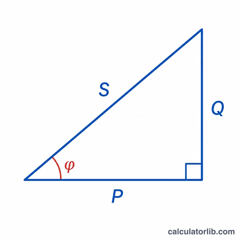
- Reactive power (Q)
- The power that oscillates between source and reactive components (inductors, capacitors) without being consumed, measured in volt-amperes reactive (VAR): \(Q = V \times I \times \sin\varphi\). The three powers relate as \(S^2 = P^2 + Q^2\).
- Power factor (cos φ)
- The dimensionless ratio of real to apparent power, \(\text{PF} = P / S = \cos\varphi\), ranging from 0 to 1. A value of 1 means all current does useful work; lower values mean wasted capacity.
- RMS voltage / current
- The root-mean-square values of an AC waveform, in volts (V) and amperes (A). RMS is the equivalent DC value producing the same heating, and is the voltage/current normally quoted (e.g. 120 V, 230 V mains).
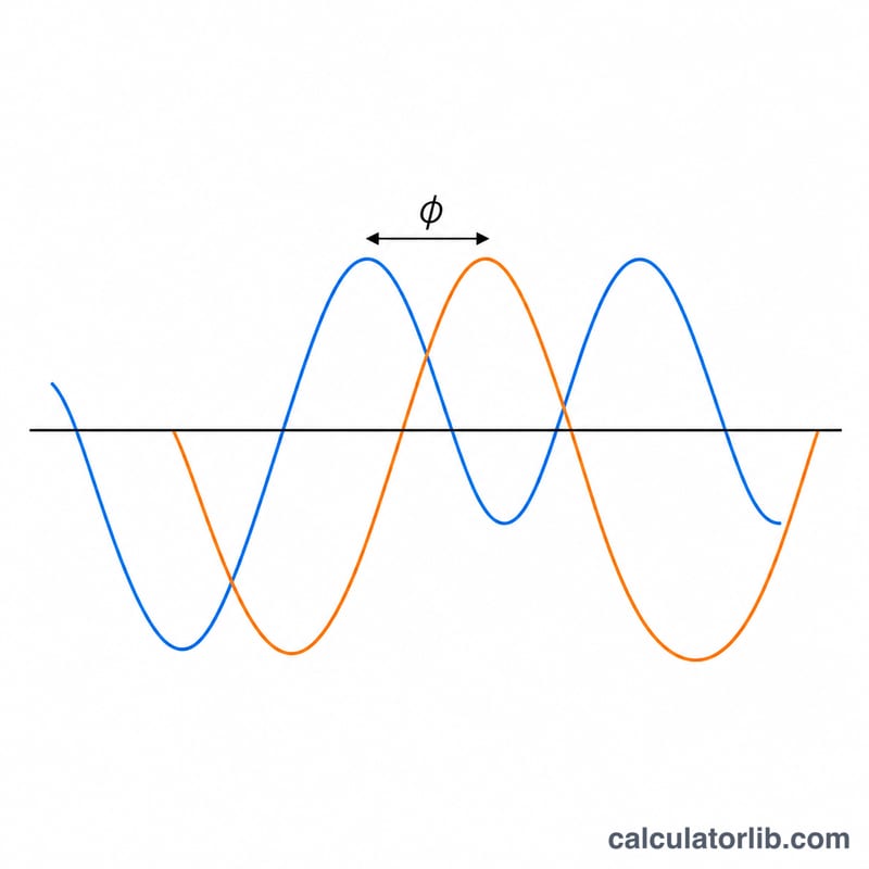
- Phase angle (φ)
- The angle in degrees (or radians) by which the current waveform lags or leads the voltage waveform. Its cosine is the power factor; \(\varphi = 0^\circ\) gives a unity power factor (purely resistive load).
FAQ
What is power factor? It is the ratio of real power to apparent power, between 0 and 1. A value of 1 means voltage and current are perfectly in phase.
What if I have a resistive load? Use a power factor of 1, so the wattage simply equals volts × amps.
Does this work for three-phase systems? No — for balanced three-phase, multiply by √3 \((P = \sqrt{3} \times V \times I \times \cos\varphi)\). This calculator is for single-phase loads.