What This Calculator Does
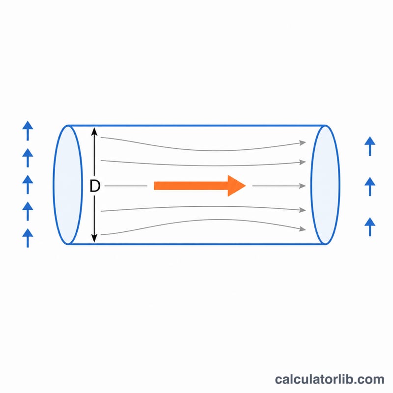
This tool estimates the volumetric air flow rate through a round duct or orifice when you know the pressure difference across it and the pipe diameter. It applies the Bernoulli energy equation to convert a measured pressure drop into an air velocity, then multiplies by the cross-sectional area and a discharge coefficient to find the flow. Results are reported in cubic meters per second, per minute, per hour, and in CFM.
The Formula Explained
The driving relationship comes from Bernoulli theorem, which links pressure to kinetic energy of the moving air:
$$v = \sqrt{\frac{2 \Delta P}{\rho}}$$where \(v\) = velocity in m/s, \(\Delta P\) = pressure difference in pascals, and \(\rho\) = air density in kg/m³ (about 1.225 at sea level, 15 °C). Once velocity is known, the flow rate is:
$$Q = C_d \cdot A \cdot v = C_d \cdot \frac{\pi d^2}{4} \cdot v$$Here \(A\) = pipe area, \(d\) = inside diameter, and \(C_d\) = discharge coefficient (typically 0.6–0.98 depending on the geometry).
How To Use It
Enter the pipe diameter and pick its unit, the pressure difference in pascals, the air density, and a discharge coefficient. The calculator converts the diameter to meters, computes the area, finds the velocity, and returns the flow rate.
Worked Example
For a 100 mm pipe with \(\Delta P = 50\,\text{Pa}\), \(\rho = 1.225\), and \(C_d = 0.98\):
$$v = \sqrt{\frac{2 \times 50}{1.225}} = 9.035\,\text{m/s}$$$$A = \frac{\pi (0.1)^2}{4} = 0.007854\,\text{m}^2$$$$Q = 0.98 \times 0.007854 \times 9.035 = 0.06954\,\text{m}^3/\text{s}$$
Discharge Coefficients for Common Geometries
The discharge coefficient \(C_d\) accounts for energy losses and flow contraction (vena contracta) that cause the actual flow to fall short of the ideal Bernoulli prediction. It is the ratio of actual to theoretical flow, and is always \(\le 1\). Choosing the right value for your geometry is the single largest source of accuracy in this calculation.
| Geometry | Typical \(C_d\) | Notes |
|---|---|---|
| Sharp-edged orifice | 0.60 – 0.62 | Strong flow contraction; the standard ~0.61 is widely used for thin-plate orifices. |
| Short tube / duct entry | 0.80 – 0.82 | Reattached flow downstream of contraction recovers some pressure. |
| Flow nozzle (ISA 1932) | ~0.96 | Smooth converging profile reduces losses considerably. |
| Venturi nozzle | 0.95 – 0.98 | Gradual contraction and diffuser; low permanent pressure loss. |
| Well-rounded / bell-mouth nozzle | 0.97 – 0.99 | Near-ideal; minimal contraction, used as a flow standard. |
When in doubt for a smooth pipe or duct entry, \(C_d \approx 0.97\text{–}0.98\) is a reasonable default; for a sharp hole in a plate, use \(C_d \approx 0.61\).
FAQ
What discharge coefficient should I use? A smooth, well-rounded nozzle is near 0.97–0.99, while a sharp-edged orifice is closer to 0.6. Use 0.98 if unsure for a duct.
Which air density should I enter? 1.225 kg/m³ is standard sea-level air at 15 °C. Use a lower value for hot air or high altitude.
Does this work for incompressible flow only? The Bernoulli form here assumes low-speed, incompressible flow, which is accurate for typical ventilation pressures well below the speed of sound.