
What is the Dipole Antenna Length Calculator?
This calculator gives you the physical length of a half-wave dipole antenna for any operating frequency. A dipole is the most common and effective wire antenna for amateur radio, shortwave listening, and many transmitting and receiving applications. Simply enter your target frequency in megahertz (MHz) and the tool returns the total span and the length of each of the two legs, in both meters and feet.
How to use it
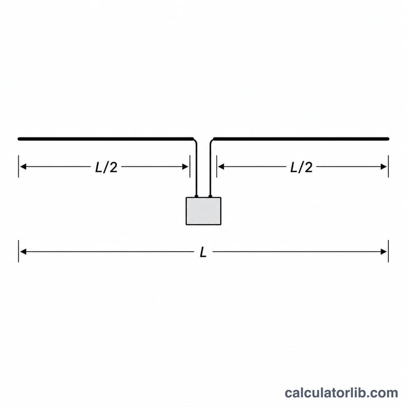
Enter the frequency you want the antenna to resonate at — for example, 14.2 MHz for the 20-meter amateur band. The calculator divides 143 by the frequency to find the total length. Cut your wire to that length, feed it in the center, and split it into two equal legs. Always cut a little long and trim to tune, since nearby objects, height above ground, and wire insulation lower the resonant frequency slightly.
The formula explained
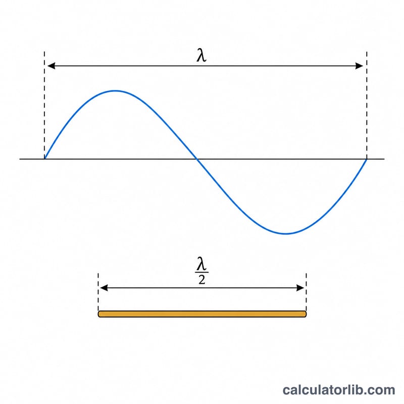
The theoretical half-wavelength in free space is \(150/f\) (MHz) in meters. Real wire antennas exhibit an "end effect" and a velocity factor of roughly 0.95, so the practical length is shortened. The widely used rule of thumb is $$L_{\text{total}} = \frac{143}{\text{Frequency (MHz)}}\ \text{m}$$ for the total span, with each leg being half of that, $$L_{\text{leg}} = \frac{L_{\text{total}}}{2} = \frac{71.5}{f(\text{MHz})}.$$ This accounts for the typical velocity factor of bare or thinly insulated copper wire.
Worked example
For a 7.1 MHz (40-meter band) dipole: $$L = \frac{143}{7.1} = 20.14 \text{ meters total},$$ or about 66.1 feet. Each leg is 10.07 meters (≈33 ft). Cut two pieces slightly longer, attach to a center insulator, and trim equally on both sides while measuring SWR.
Key Terms Explained
- Half-wave dipole
- A center-fed antenna whose total length is approximately one half of the operating wavelength, split into two equal legs of a quarter wavelength each. It is the reference antenna against which gain (dBd) is often measured.
- Resonant frequency
- The frequency at which the antenna's reactance is near zero and it presents a mostly resistive feed-point impedance (about 73 Ω in free space). At resonance SWR is lowest and power transfer is most efficient.
- Velocity factor (VF)
- The ratio of wave speed along the conductor to the speed of light in free space. For bare wire it is roughly 0.95–0.98; insulation and conductor effects make the physical antenna slightly shorter than a free-space half wavelength.
- End effect
- Capacitive loading at the open ends of the wire that makes the antenna behave as if it were electrically longer than its physical length, requiring the wire to be cut about 2–5% shorter than the ideal free-space half wave.
- SWR (Standing Wave Ratio)
- A measure of impedance match between the feed line and antenna. 1:1 is perfect; higher values mean more reflected power. SWR is used to find and confirm resonance during tuning.
- Center insulator / feed point
- The middle of the dipole where the two legs meet and the coaxial feed line connects. This is the voltage minimum / current maximum point and the natural place for the feed and any balun.
- Balun
- A “balanced-to-unbalanced” transformer placed at the feed point to connect an unbalanced coax line to the balanced dipole. It suppresses common-mode current flowing on the outside of the coax shield, reducing pattern distortion and RF in the shack.
- Electrical vs physical length
- Electrical length is how long the antenna appears to the radio wave (in degrees or wavelengths); physical length is the tape-measure length of the wire. End effect and velocity factor make the physical length shorter than the electrical length.
FAQ
Why 143 instead of 150? The 150 figure is the ideal free-space half-wave. The factor 143 builds in the ~0.95 velocity factor and end effect of real wire so the antenna resonates close to your target without much trimming.
What is each leg length? A center-fed dipole has two equal legs; each is half the total, so \(\text{leg} = 71.5 / f(\text{MHz})\).
Should I cut exactly to this length? Cut about 2–3% longer and trim to tune. Height, surroundings, and wire type shift resonance, so final tuning with an SWR meter or antenna analyzer is recommended.