What is a J-Pole Antenna?
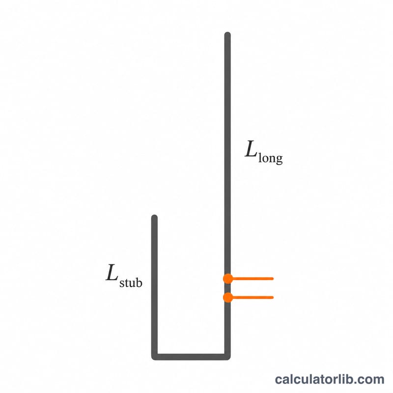
The J-pole is a popular end-fed, half-wave antenna for amateur (ham) radio and VHF/UHF use. It needs no radials or ground plane and is simple to build from copper pipe, ladder line, or twin-lead. The design consists of a long radiating element (about three-quarters of a wavelength) and a short parallel matching stub (about one-quarter wavelength) that together form a J shape and provide a convenient 50-ohm feed point.
How to Use This Calculator
Enter your operating frequency in megahertz (MHz) and the velocity factor of your conductor. For solid bare copper pipe a velocity factor near 0.95 is typical; for insulated wire or ladder line it may be lower (0.80–0.90). The calculator returns the long element and matching stub lengths in feet, inches, and centimeters. Build slightly long and trim for lowest SWR.
The Formula Explained
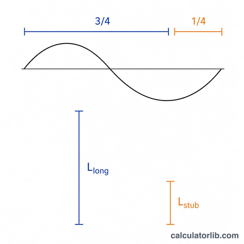
The classic half-wave dipole approximation gives a quarter wavelength in feet as 234/f(MHz). The J-pole long element is roughly 3λ/4, so we use 234/f, while the matching stub is λ/4, giving 78/f. Both are multiplied by the velocity factor (VF) to account for the wave traveling slightly slower in the conductor:
$$L_{\text{long}} = \frac{234}{\text{Frequency (MHz)}} \times \text{Velocity Factor} \quad\text{(feet)}$$and
$$L_{\text{stub}} = \frac{78}{\text{Frequency (MHz)}} \times \text{Velocity Factor} \quad\text{(feet)}$$.
Worked Example
For the 2-meter band at 146 MHz with VF = 0.95: long element =
$$L_{\text{long}} = \frac{234}{146} \times 0.95 = 1.603 \times 0.95 \approx 1.523 \text{ ft (about 18.3 in)}$$The stub =
$$L_{\text{stub}} = \frac{78}{146} \times 0.95 = 0.534 \times 0.95 \approx 0.5075 \text{ ft (about 6.1 in)}$$Cut a bit long and trim while watching your SWR meter.
FAQ
What velocity factor should I use? Bare copper pipe: ~0.95. Insulated wire/ladder line: ~0.80–0.90. When unsure, start at 0.95 and trim.
Why build slightly long? You can always trim metal off to raise the resonant frequency, but you cannot easily add it back. Start long and shorten in small steps.
Where does the coax connect? The feed point is a small distance up the matching stub (often 1–3 inches above the bottom shorting bar). Slide the connection to fine-tune SWR.