What is a Low Pass Filter Calculator?
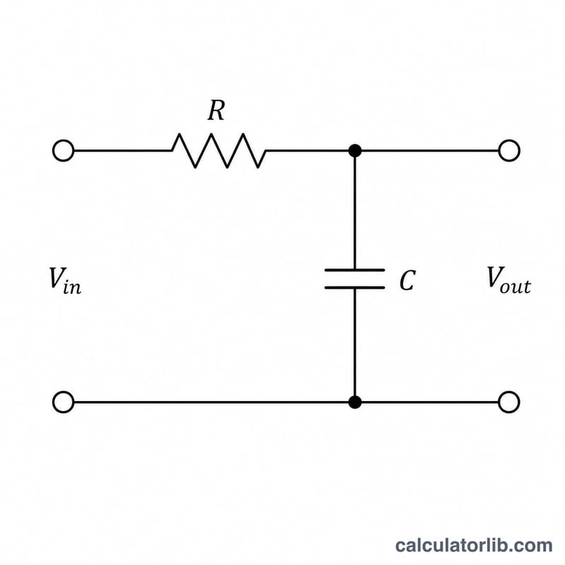
A low pass filter passes low-frequency signals while attenuating frequencies above its cutoff point. The most common type is the passive first-order RC filter, built from a single resistor and capacitor. This calculator finds the cutoff frequency (the −3 dB point) along with the time constant and angular frequency from the component values you enter.
How to use it
Enter the resistance R in ohms and the capacitance C in microfarads (µF). The calculator converts the capacitance to farads internally and returns the cutoff frequency in hertz. Use it to design audio crossovers, anti-aliasing filters, noise-reduction stages, or sensor signal conditioning.
The formula explained
The cutoff frequency is given by:
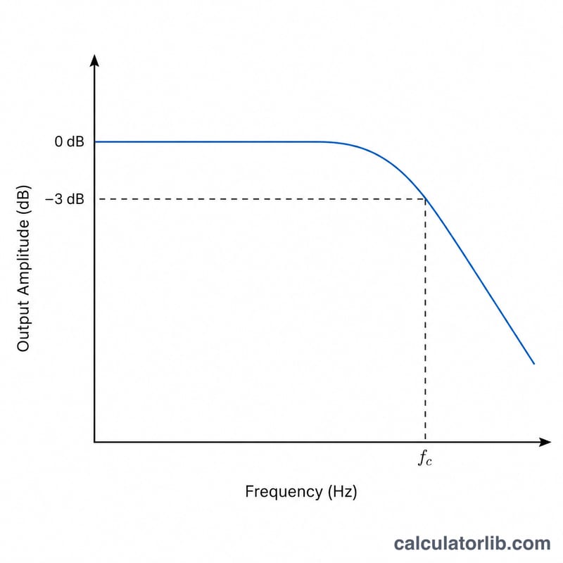
$$f_c = \frac{1}{2\pi \cdot \text{R }(\Omega) \cdot \text{C }(\mu F) \times 10^{-6}}$$At this frequency the filter's output power drops to half (−3 dB) of the input. Below \(f_c\) signals pass nearly unchanged; above it they roll off at 20 dB per decade. The time constant \(\tau = R \times C\) describes how fast the circuit charges, and the angular cutoff is \(\omega = 2\pi f_c\).
Worked example
With R = 1,000 \(\Omega\) and C = 0.1 µF (\(1 \times 10^{-7}\) F):
$$f_c = \frac{1}{2\pi \times 1000 \times 0.0000001} = \frac{1}{0.000628318} \approx 1591.55 \text{ Hz}$$The time constant \(\tau = 1000 \times 0.0000001 = 0.0001\ \text{s} = 0.1\ \text{ms}\).
FAQ
What is the −3 dB point? It is the frequency where the output amplitude falls to about 70.7% of the input, marking the edge of the passband.
Does this work for an LC or active filter? No — this tool models a simple first-order passive RC filter. Other topologies use different equations.
Why microfarads? Most capacitors used in filters are in the nano- to microfarad range, so µF keeps the input convenient. The tool converts to farads before computing.