What Is an LC Filter Calculator?
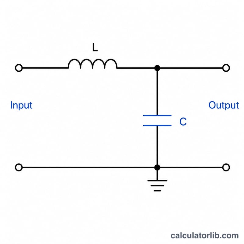
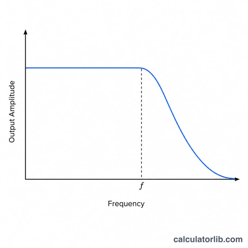
An LC filter combines an inductor (L) and a capacitor (C) to pass or block signals based on frequency. This calculator finds the resonant (cutoff) frequency—the point where the reactance of the inductor equals that of the capacitor and the filter most strongly affects the signal. It applies universally to electronics worldwide, independent of any country or standard.
How to Use It
Enter the inductance in microhenries (µH) and the capacitance in microfarads (µF). The tool converts both to base SI units (henries and farads) and returns the frequency in hertz, plus a convenient kilohertz value. Use it for designing low-pass, high-pass, band-pass filters, LC tank circuits, and oscillators.
The Formula Explained
The resonant frequency is given by:
$$f_c = \frac{1}{2\pi \sqrt{\left(\text{L (µH)} \times 10^{-6}\right)\left(\text{C (µF)} \times 10^{-6}\right)}}$$
Here \(L\) is inductance in henries and \(C\) is capacitance in farads. Because the product \(LC\) sits inside a square root, doubling either \(L\) or \(C\) lowers the frequency by a factor of about 1.41 (\(\sqrt{2}\)). Increasing the component values lowers the cutoff frequency; decreasing them raises it.
Worked Example
Suppose \(L = 100\) µH (0.0001 H) and \(C = 10\) µF (0.00001 H). Then \(LC = 1\times 10^{-9}\), and \(\sqrt{LC} \approx 3.162\times 10^{-5}\). So $$f = \frac{1}{2\pi \times 3.162\times 10^{-5}} \approx \frac{1}{1.987\times 10^{-4}} \approx 5033 \text{ Hz},$$ or about 5.03 kHz.
FAQ
Is this the cutoff or resonant frequency? For an LC tank it is the resonant frequency; for a simple second-order LC filter it is the −3 dB corner frequency. They share the same formula.
What units should I use? Enter µH and µF. The calculator converts to henries and farads internally.
Does component resistance matter? Ideal LC resonance ignores resistance. Real circuits have a quality factor (Q) that affects bandwidth but not the center frequency much.