What is the RC Filter Cutoff Frequency Calculator?
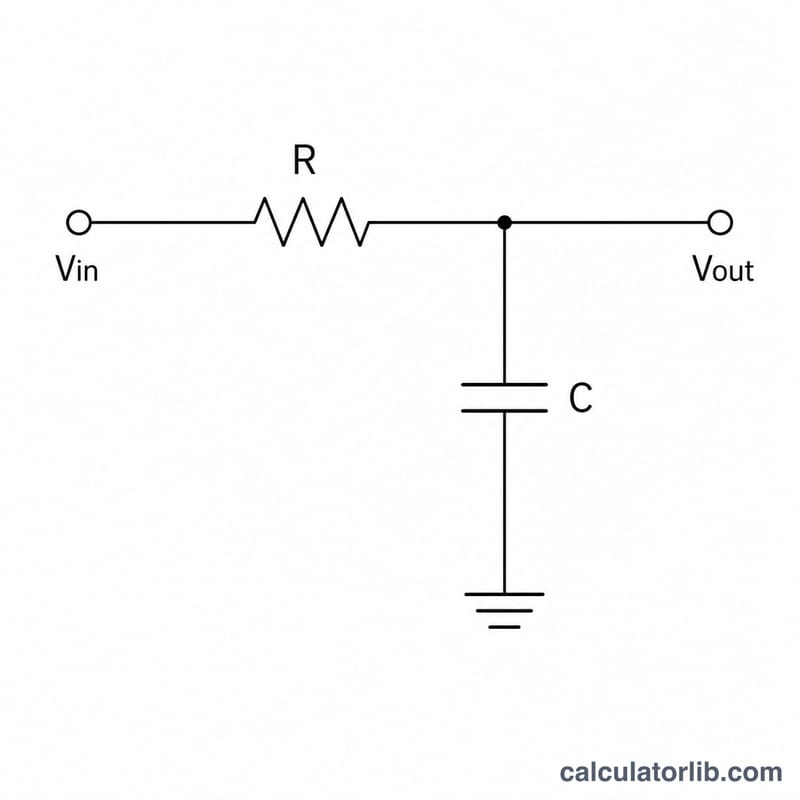
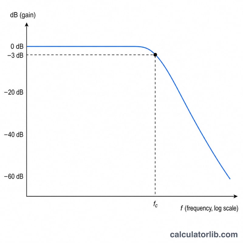
An RC filter is the simplest passive electronic filter, built from one resistor (R) and one capacitor (C). Depending on how the output is taken, it acts as a low-pass filter (passes low frequencies) or a high-pass filter (passes high frequencies). This calculator finds the cutoff frequency — also called the corner or −3 dB frequency — the point where the signal power drops to half (output amplitude falls to about 70.7% of the input).
How to use it
Enter the resistance in ohms (Ω) and the capacitance in farads (F). Remember common prefixes: 1 kΩ = 1000 Ω, 1 µF = 0.000001 F, 1 nF = 0.000000001 F, 1 pF = 1e-12 F. The calculator returns the cutoff frequency in hertz, plus the time constant τ and the angular cutoff frequency ω.
The formula explained
The cutoff frequency is given by:
$$f_c = \frac{1}{2\pi \text{R }(\Omega) \cdot \text{C (F)}}$$
Larger resistance or capacitance lowers the cutoff frequency, while smaller values raise it. The related time constant is \(\tau = R \cdot C\), and the angular cutoff frequency is \(\omega = 2\pi f_c = \frac{1}{RC}\).
Worked example
Take R = 1000 Ω and C = 1 µF (0.000001 F). Then $$f_c = \frac{1}{2 \times \pi \times 1000 \times 0.000001} = \frac{1}{0.006283\ldots} \approx 159.15 \text{ Hz}$$ The time constant is \(\tau = 1000 \times 0.000001 = 0.001 \text{ s}\) (1 ms).
FAQ
Is this for low-pass or high-pass filters? Both. A first-order RC low-pass and high-pass filter share the same cutoff frequency formula; only the circuit topology differs.
What does −3 dB mean? At the cutoff frequency the output power is half the input power, equal to a 3 decibel drop, and the voltage gain is \(\frac{1}{\sqrt{2}} \approx 0.707\).
What units should I use? Always convert to base SI units: ohms for R and farads for C. Convert µF, nF, pF to farads before entering.