What This Calculator Does
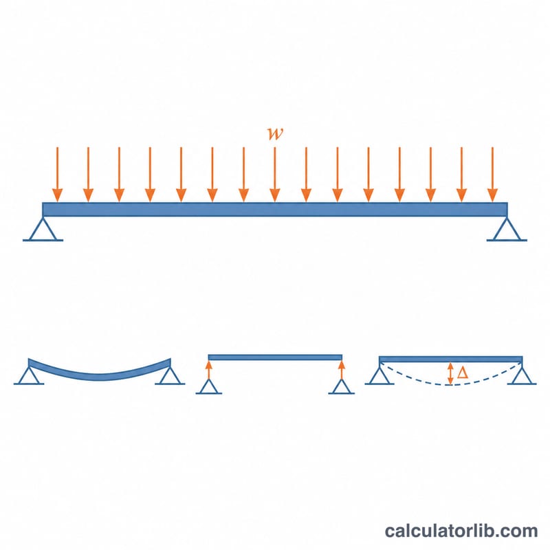
Applies to the United States. This tool estimates how far a solid or built-up deck beam can span between posts, using design values for visually graded No. 2 dimension lumber and the usual residential deck loading of 40 psf live plus 10 psf dead. Assumptions: a simple (single) span, uniform load, dry service conditions, normal load duration, and beam plies properly nailed or bolted together so they act as one member. It is a preliminary sizing aid, not a substitute for IRC Table R507.5, AWC DCA 6, or a design stamped by a licensed engineer.
How to Use It
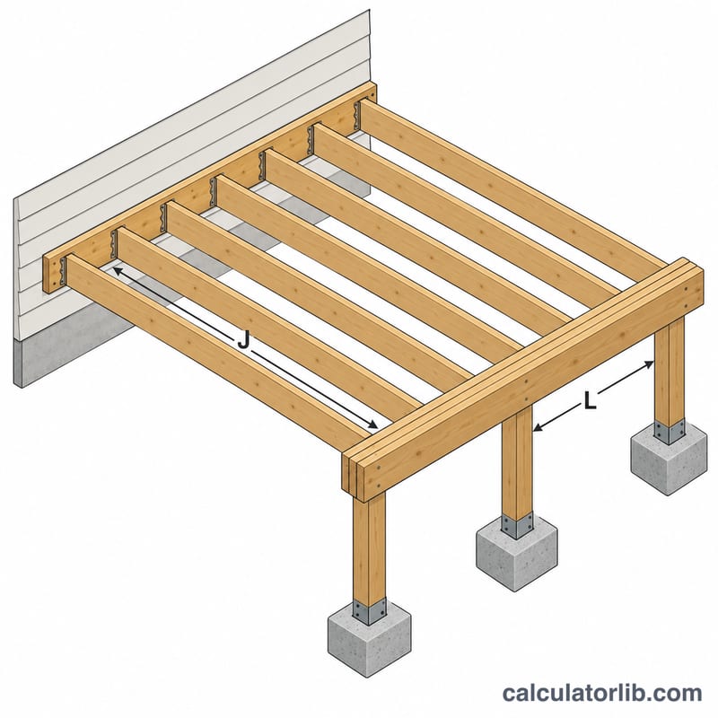
Pick the beam lumber size and how many plies you plan to laminate, choose the species and grade of the lumber you can actually buy locally, then enter the joist span the beam supports — that is the clear distance the joists cross, not the deck width. Leave the loads at 40 and 10 psf for a normal residential deck, or raise the live load for a hot tub, planters, or heavy snow. The result is the longest post spacing the beam can carry, plus the span allowed by each separate check so you can see what is controlling.
The Formula Explained
The beam carries half the joist span on each side of it, so the load per linear foot is
$$w = (w_L + w_D)\times\frac{S_j}{2}$$where \(w_L\) = live load in psf, \(w_D\) = dead load in psf and \(S_j\) = joist span in feet. Bending usually controls, giving
$$L_b = \sqrt{\frac{2\,F_b^{\prime}\,S}{3\,w}},\qquad S = \frac{n\,b\,d^2}{6}$$with \(F_b^{\prime}\) the adjusted bending design value in psi, \(n\) the ply count, \(b = 1.5\) in per ply and \(d\) the actual depth. Shear and an L/360 live-load deflection limit are checked too, and the smallest of the three spans is reported.
Worked Example
A 3-ply 2x10 Douglas Fir-Larch No. 2 beam supporting a 12 ft joist span:
$$w = (40 + 10)\times\frac{12}{2} = 300\ \text{lb/ft}$$$$S = \frac{4.5\times 9.25^2}{6} = 64.17\ \text{in}^3$$$$L_b = \sqrt{\frac{2\times 990\times 64.17}{3\times 300}} = 11.88\ \text{ft}$$Shear allows 33.3 ft and deflection 14.3 ft, so bending governs at about 11 ft 10 in between post centres.
Lumber Design Values by Species and Grade
This calculator is built around the United States design framework: reference design values from the AWC NDS Supplement, Table 4A (visually graded dimension lumber, 2"–4" thick) and Table 4B (Southern Pine), with the 40 psf live / 10 psf dead deck loading used by the US International Residential Code (IRC). Values below are base reference design values before adjustment, and they vary by grading agency, grade stamp and size category — always read the actual grade stamp on the lumber you buy.
| Species group (US market) | Grade | Fb bending (psi) | Fv shear (psi) | E modulus (psi) |
|---|---|---|---|---|
| Douglas Fir-Larch | No. 1 | 1,000 | 180 | 1,700,000 |
| Douglas Fir-Larch | No. 2 | 900 | 180 | 1,600,000 |
| Hem-Fir | No. 1 | 975 | 150 | 1,500,000 |
| Hem-Fir | No. 2 | 850 | 150 | 1,300,000 |
| Spruce-Pine-Fir | No. 1 / No. 2 (graded together) | 875 | 135 | 1,400,000 |
| Southern Pine | No. 2 | varies by width, roughly 775–1,100 (see note) | 175 | 1,600,000 |
Southern Pine is tabulated differently. Since the 2013 SPIB revision, Southern Pine bending values in NDS Table 4B are listed separately for each width (2x4 highest, 2x12 lowest) because the size effect is built into the table. For that reason the size factor is taken as \(C_F = 1.0\) for Southern Pine dimension lumber, while the other species groups get an explicit size factor.
Size factor CF applied to Fb (No. 1 / No. 2, Douglas Fir-Larch, Hem-Fir, Spruce-Pine-Fir)
| Nominal depth | 2x6 | 2x8 | 2x10 | 2x12 |
|---|---|---|---|---|
| CF for Fb | 1.30 | 1.20 | 1.10 | 1.00 |
The size factor is applied to bending only; \(C_F = 1.0\) for shear \(F_v\) and for modulus of elasticity \(E\). So the adjusted bending value used in the span equation is \(F_b' = F_b \times C_F \times C_D \times C_M\).
Adjustment factors used in this calculation
- CD = 1.0 — load duration factor for normal (10-year) duration, the correct choice for residential floor and deck live load.
- CM = 1.0 — wet service factor for dry service (moisture content 19% or less). Note that NDS Table 4A permits \(C_M = 1.0\) for bending whenever \(F_b \cdot C_F \le 1{,}150\) psi, which covers most No. 2 deck beams; for higher bending values in genuinely wet service the factors are 0.85 for \(F_b\), 0.97 for \(F_v\) and 0.90 for \(E\).
- Cr = 1.0 (not applied) — the 1.15 repetitive member factor only applies to bending members spaced 24 in. on center or less in groups of three or more sharing a load-distributing deck. Deck joists normally qualify; a single beam line does not, so it is deliberately excluded here.
- Ci = 1.0 (not applied) — if your lumber is pressure-treated and incised, NDS Table 4.3.8 requires an incising factor of 0.80 on \(F_b\) and \(F_v\) and 0.95 on \(E\), which shortens the allowable span. Incising is common on refractory species such as Douglas Fir and Hem-Fir.
- CL = 1.0 — assumes the beam top edge is restrained by joists and blocking so lateral-torsional buckling does not govern.
The "cedar" option represents Western Cedars / Western Red Cedar No. 2, which is substantially weaker and far less stiff than the framing species above (on the order of 700 psi bending and about 1,000,000 psi modulus of elasticity). Cedar is a decking and trim material in US practice, not a normal beam material; expect short allowable spans.
Actual Beam Dimensions and Section Modulus
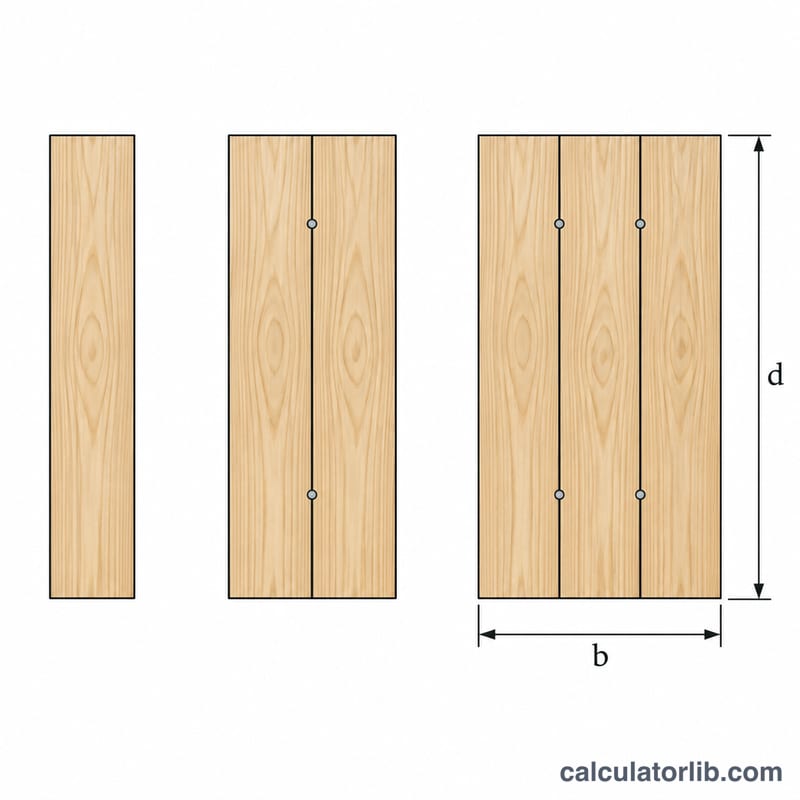
US lumber is sold by nominal size but designed with actual dressed (S4S) dimensions per the American Lumber Standard, PS 20. A 2x build-up is 1.5 in. thick per ply, so a built-up beam of \(n\) plies has width \(b = 1.5n\) and the section properties below.
$$S = \frac{n\,b_1 d^{2}}{6}, \qquad A = n\,b_1 d, \qquad I = \frac{n\,b_1 d^{3}}{12}, \qquad b_1 = 1.5\ \text{in}$$
| Nominal | Actual (in) | Plies | Width b (in) | Area A (in²) | Section modulus S (in³) | Moment of inertia I (in⁴) |
|---|---|---|---|---|---|---|
| 2x6 | 1.5 × 5.5 | 2 | 3.0 | 16.50 | 15.13 | 41.59 |
| 2x6 | 1.5 × 5.5 | 3 | 4.5 | 24.75 | 22.69 | 62.39 |
| 2x8 | 1.5 × 7.25 | 2 | 3.0 | 21.75 | 26.28 | 95.27 |
| 2x8 | 1.5 × 7.25 | 3 | 4.5 | 32.63 | 39.42 | 142.90 |
| 2x10 | 1.5 × 9.25 | 2 | 3.0 | 27.75 | 42.78 | 197.86 |
| 2x10 | 1.5 × 9.25 | 3 | 4.5 | 41.63 | 64.17 | 296.80 |
| 2x12 | 1.5 × 11.25 | 2 | 3.0 | 33.75 | 63.28 | 355.96 |
| 2x12 | 1.5 × 11.25 | 3 | 4.5 | 50.63 | 94.92 | 533.94 |
Depth matters far more than width: section modulus grows with \(d^{2}\) and stiffness with \(d^{3}\). Going from a 2-ply 2x8 to a 2-ply 2x10 raises S by about 63% and I by more than 100%, while adding a third 2x8 ply raises both by only 50%.
Solid 4x and 6x timbers are not the same as multi-ply
A nominal 4x member dresses to 3.5 in. thick and a 6x to 5.5 in. thick, so they do not match built-up equivalents: a solid 4x8 (3.5 × 7.25 in.) has about 17% more section than a 2-ply 2x8 (3.0 × 7.25 in.), and a solid 6x8 is wider than a 3-ply build-up (5.5 vs. 4.5 in.). They also carry different design values — 4x lumber is still dimension lumber under NDS Table 4A but uses the 4"-thick size factors, while 5x5 and larger falls into the Posts & Timbers / Beams & Stringers classifications of NDS Table 4D, with lower bending values than No. 2 dimension lumber in several species. This tool models 1.5 in. plies only, so do not enter a 4x or 6x timber by converting it to an equivalent ply count.
Worked example — 2-ply 2x10 Douglas Fir-Larch No. 2
Inputs: 2x10, 2 plies, Douglas Fir-Larch, joist span 12 ft, 40 psf live, 10 psf dead.
- Tributary load: \(w = (40 + 10) \times \dfrac{12}{2} = 300\ \text{lb/ft}\); live-load only \(w_L = \dfrac{40 \times 12}{24} = 20\ \text{lb/in}\).
- Adjusted bending value: \(F_b' = 900 \times 1.10 = 990\ \text{psi}\); \(S = 42.78\ \text{in}^3\), \(A = 27.75\ \text{in}^2\), \(I = 197.86\ \text{in}^4\), \(E = 1{,}600{,}000\ \text{psi}\).
- Bending: \(L_b = \sqrt{\dfrac{2 \times 990 \times 42.78}{3 \times 300}} = \sqrt{94.12} = 9.70\ \text{ft}\).
- Shear: \(L_v = \dfrac{4 \times 180 \times 27.75}{3 \times 300} = \dfrac{19{,}980}{900} = 22.2\ \text{ft}\).
- Deflection (L/360 live load): \(L_{\Delta} = \dfrac{1}{12}\sqrt[3]{\dfrac{384 \times 1{,}600{,}000 \times 197.86}{1800 \times 20}} = \dfrac{150.0}{12} = 12.50\ \text{ft}\).
Bending governs, so the maximum allowable span is \(L_{\max} = \min(9.70,\ 22.2,\ 12.50) =\) 9.70 ft. Shear is rarely the controlling limit for deck beams of these proportions; bending and deflection almost always decide the answer.
Applying the Result on Site
The calculated span is a clean-math allowable length, not a construction dimension. Turn it into a buildable layout like this.
- Round down, never up. A result of 9.70 ft becomes a 9 ft — or more conveniently an 8 ft — post spacing. Rounding 9.70 up to 10 ft puts the beam over its own limit before you add a single fastener.
- Cross-check the prescriptive tables and build to the shorter number. In the US, IRC Table R507.5 and the AWC DCA 6 – Prescriptive Residential Wood Deck Construction Guide list beam spans by size, species and joist span. Those tables fold in extra conservatism and simplifying assumptions that an engineering calculation does not, so they are frequently shorter than the computed value. Inspectors enforce the table, not your arithmetic — if the table is shorter, the table wins. Outside the United States, use your own national code (for example the relevant CSA, Eurocode/EN or AS/NZS provisions) instead; the 40/10 psf loading and the values behind this tool are US-specific.
- Convert span to post and footing count. Divide the deck length carried by the beam by the allowable span and round the number of bays up: \(\text{bays} = \lceil 24 \div 9 \rceil = 3\) for a 24 ft beam at a 9 ft limit, giving 3 equal 8 ft bays, 4 posts and 4 footings. If the deck length exceeds the allowable span at all, you need at least one interior post — two end posts alone are not an option.
- Use cantilevers deliberately, within the limit. Running the beam past the end posts shortens the clear span between them. US prescriptive practice caps that overhang at one-quarter of the backspan, so a 9 ft span allows at most about 2 ft 3 in. of beam beyond the post. Cantilevering the joists past the beam is a separate check with its own limit.
- Fasten built-up plies as a structural assembly. Two or three 2x plies only act as one beam if they are connected along their full length. Use through-bolts with washers or code-listed structural screws in two staggered rows, with fasteners near each end and at a regular spacing along the length, per the schedule in DCA 6 or the screw manufacturer's evaluation report. Field nails alone are not an equivalent substitute, and plies should be oriented crown-up and tight. For exterior work, every fastener and connector must be rated for contact with the preservative treatment you are using (typically hot-dip galvanized or stainless).
- Check the connections and the posts separately — this calculator does not. The span check only verifies the beam between supports. You still have to confirm the rated capacity of the post cap or saddle, the bearing area where the beam sits on the post (compression perpendicular to grain in the beam, compression parallel to grain in the post), post size and unbraced height, lateral bracing, and the footing size against your soil bearing value and frost depth. Any one of these can be the real weak link.
- Get it approved before you pour. Take the size, species, grade, joist span, beam span and post layout to your local building department. Local amendments, snow or seismic provisions, high-wind rules and guard-load requirements routinely override the generic case, and footings are the hardest thing on a deck to change later.
Two habits that pay for themselves: specify the species and grade you can actually buy locally before you finalize the layout (substituting Spruce-Pine-Fir for Douglas Fir-Larch at the lumberyard changes the answer), and check the grade stamp on delivery. If the lumber shows up incised or a grade lower than you assumed, rerun the numbers.
This is general construction information, not engineering advice for your specific project. For irregular geometry, point loads such as hot tubs or planters, elevated or multi-level decks, or anything outside the prescriptive tables, have a licensed design professional in your jurisdiction size the beam.
FAQ
Why is my answer longer than the code table? Published tables round down and bundle in extra conservatism for bearing, connections and tributary assumptions. Always build to the table value if it is shorter.
Does a 3-ply beam span 1.5 times a 2-ply? No. Bending span grows with the square root of width, so adding a third ply gains roughly 22 percent, not 50 percent.
Can I use this for a cantilevered or continuous beam? No. The math here is for a simple span between two posts; cantilevers and multi-span beams need a separate analysis.