What is a fixed-end beam?
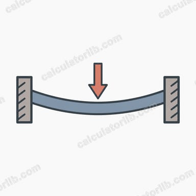
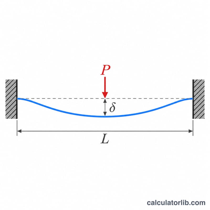
A fixed-end (fixed-fixed or built-in) beam is restrained against both rotation and translation at each support. Compared with a simply supported beam, the end restraints create negative bending moments at the supports and greatly reduce midspan deflection. This calculator gives the maximum deflection and the largest fixed-end moment for three common load cases, using SI units.
How to use the calculator
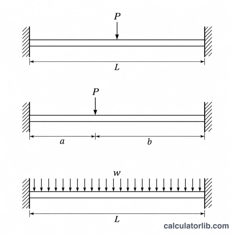
Choose the load type, then enter the load (newtons for a point load, newtons per metre for a distributed load), the span length in metres, the elastic modulus E in GPa (steel is about 200 GPa, aluminium about 69 GPa) and the second moment of area I in cm^4. For an off-center load also enter the distance a from the left support. The result is given in millimetres together with the L/δ ratio, which you can compare with serviceability limits such as L/360.
The formulas
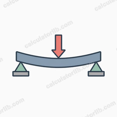
For a central point load \(P\) on a span \(L\):
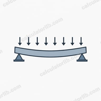
$$\delta_{max} = \frac{P L^{3}}{192 E I}$$For a uniformly distributed load \(w\):
$$\delta_{max} = \frac{w L^{4}}{384 E I}$$For a point load at distance \(a\) from one end, with \(s\) the shorter and \(l\) the longer segment:
$$\delta_{max} = \frac{2 P s^{2} l^{3}}{3 E I (3l + s)^{2}}$$Fixed-end moments are \(PL/8\) (central load), \(wL^{2}/12\) (uniform load) and \(P a b^{2}/L^{2}\) or \(P a^{2} b/L^{2}\) (off-center load, the larger governs). EI is computed as \(E\,[\text{GPa}] \times I\,[\text{cm}^4] \times 10\) in N·m².
Worked example
A steel beam (\(E = 200\) GPa, \(I = 8000\) cm^4) spans \(L = 4\) m with a 10,000 N load at midspan. Then \(EI = 16{,}000{,}000\) N·m².
$$\delta_{max} = \frac{10000 \times 4^{3}}{192 \times 16{,}000{,}000} = 2.083 \times 10^{-4}\,\text{m} = 0.208\,\text{mm}$$The span-to-deflection ratio is about 19,200, far stiffer than typical limits.
Typical Elastic Modulus Values for Common Beam Materials
The calculator needs Young's modulus E in GPa. The values below are approximate, typical figures for comparison only. Use the actual grade, species or design-code value for real design work.
| Material | Typical E (GPa) |
|---|---|
| Structural steel | ≈ 200 |
| Stainless steel (austenitic) | ≈ 193 |
| Aluminium alloys | ≈ 69 |
| Cast iron | ≈ 100–170 (varies with type) |
| Timber | ≈ 8–14 (depends on species and grade) |
| Concrete | ≈ 25–35 (depends on strength class) |
| Titanium | ≈ 110 |
| Copper | ≈ 110–120 |
Note that the calculator converts E (GPa) × I (cm⁴) into EI in N·m² using the factor 10, because 1 GPa × 1 cm⁴ = 10⁹ Pa × 10⁻⁸ m⁴ = 10 N·m².
Interpreting the Deflection and L/δ Result
The L/δ value is the span-to-deflection ratio: the span divided by the maximum deflection, both in the same unit. A larger number means a stiffer response. For example, a 4 m span deflecting 8 mm gives \(L/\delta = 4000/8 = 500\), i.e. L/500.
Commonly cited serviceability limits (deflection ≤ span divided by the number) are:
- L/180 – general or cantilever-type roofs where finishes are not sensitive
- L/240 – general limit for many members
- L/360 – floors with plaster or other brittle finishes, usually checked under live load
- L/480 – floors or members with sensitive finishes
- L/600 or more – supports for sensitive equipment, where the manufacturer's tolerance may govern
Limits vary by building code, material and application, so check the standard that applies to your project.
What the result does not include: the calculator gives only elastic bending deflection. It ignores shear deformation, the beam's own self-weight (unless you add it to the load), creep (important for timber and concrete), cracking, and partial fixity. Real supports are rarely perfectly rigid, so true deflection is usually somewhat larger than the fully fixed result.
Fixed-end moment: this is the hogging (negative) moment developed at each support. It is used to check strength (bending stress and the support connection design) and is a separate check from deflection. A beam can pass the deflection limit and still fail on strength, or the other way round, so check both.
FAQ
Does this include self-weight?
No. Add the beam weight as a distributed load if it matters.
Does it include shear deflection?
No. It uses Euler-Bernoulli bending theory, which is accurate for slender beams with a span-to-depth ratio above about 10.
Why is the deflection so small compared with a simply supported beam?
End fixity makes the beam four times stiffer for a central point load and five times stiffer for a uniform load, since the simple-span deflection coefficients are 1/48 and 5/384.