What this calculator does
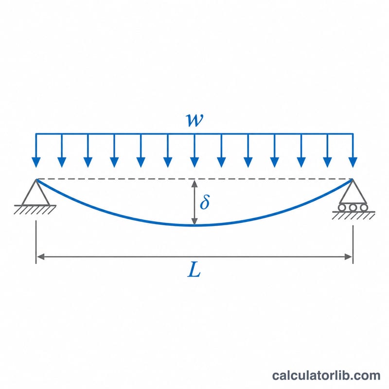
This tool estimates the maximum deflection of a straight, prismatic beam carrying a uniformly distributed load (UDL), using classical Euler-Bernoulli beam theory. Pick the support condition, enter the span, the load per metre, the material and the cross-section size, and it returns the peak deflection in millimetres together with the second moment of area, the span-to-deflection ratio and the maximum bending moment.
How to use it
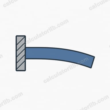
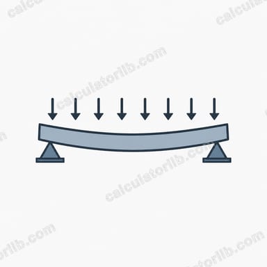
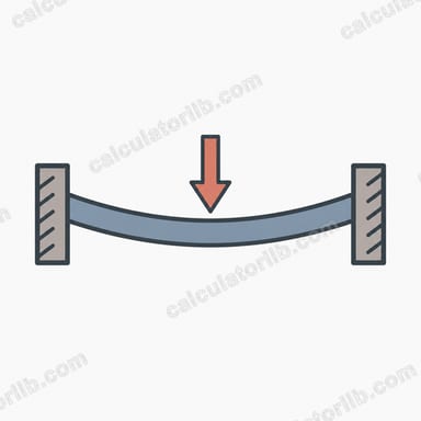
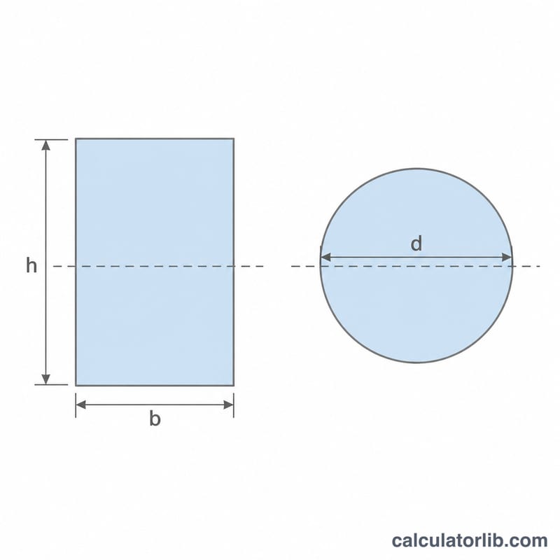
Choose simply supported, cantilever or fixed-fixed. Enter the length in metres and the load in kN/m (include the self-weight of the beam if it matters). Select a material for a typical Young modulus, or choose Custom and type E in GPa. Then enter the rectangle width and depth in mm, or the diameter for a solid circle. Only the dimensions for the selected shape are used.
The formulas explained
Deflection depends on the load, the fourth power of the span, and the flexural stiffness \(EI\):
$$\delta_{max} = \frac{k\,w L^{4}}{E I}$$where \(k = 5/384\) for a simply supported beam, \(1/8\) for a cantilever and \(1/384\) for a beam fixed at both ends. \(w\) is the load per unit length, \(L\) the span, \(E\) the Young modulus and \(I\) the second moment of area: \(I = bh^{3}/12\) for a rectangle and \(I = \pi d^{4}/64\) for a circle.
Worked example
A simply supported steel beam, \(L = 4\) m, \(w = 10\) kN/m (10 N/mm), \(E = 200\) GPa, section 100 mm by 200 mm:
$$I = \frac{100 \times 200^{3}}{12} = 6.667\times10^{7}\,\text{mm}^4$$$$\delta_{max} = \frac{5 \times 10 \times 4000^{4}}{384 \times 200000 \times 6.667\times10^{7}} = 2.5\,\text{mm}$$The span-to-deflection ratio is 4000 / 2.5 = 1600, which is better than the common L/360 limit for floors.
Typical Young's Modulus Values by Material
Young's modulus (E) measures a material's stiffness in the elastic range. Deflection is inversely proportional to E, so doubling E halves the deflection. The values below are typical approximations; actual figures vary with alloy, grade, moisture content (timber), mix and age (concrete), and the design standard being used. Always take E from the relevant material specification for design work.
| Material | Typical E (GPa) |
|---|---|
| Structural steel | 200–210 |
| Stainless steel | 190–200 |
| Aluminium alloys | 69–70 |
| Softwood timber | 7–12 |
| Hardwood timber | 10–15 |
| Concrete | 25–35 |
| Cast iron | 100–170 |
| Copper | 110–130 |
Note: in the calculator, the preset options (200, 69, 11, 30 GPa) are representative mid-range values for steel, aluminium, timber and concrete. Choose "custom" to enter a specific E in GPa.
Typical Deflection Limits (Span/Deflection Ratios)
Serviceability limits are usually expressed as a fraction of the span L. The maximum allowable deflection is \(\delta_{allow} = L / n\), where n is the ratio. Commonly used indicative values:
| Application | Typical limit |
|---|---|
| Roofs with no ceiling | L/180 |
| General roofs / ceilings | L/240 |
| Floors under live load (plaster ceilings) | L/360 |
| Floors with sensitive finishes or partitions | L/480 |
| Cantilevers | L/180 to L/150 (typically, based on cantilever length) |
These limits vary by building code and load case (for example the International Building Code in the US, or the Eurocode National Annex of each country), and by whether live load only or total load is checked. Treat them as indicative only and confirm the requirements that apply to your project and jurisdiction.
Deflection Coefficients for Other Support Conditions
For a uniformly distributed load w (force per unit length) over span L, with constant E and I, the standard results are:
| Support condition | Max deflection | Location of max deflection | Max bending moment | Max shear |
|---|---|---|---|---|
| Simply supported | \(\frac{5}{384}\frac{wL^4}{EI}\) | Midspan | \(wL^2/8\) at midspan | \(wL/2\) at supports |
| Cantilever | \(\frac{1}{8}\frac{wL^4}{EI}\) | Free end | \(wL^2/2\) at the fixed support | \(wL\) at the fixed support |
| Fixed–fixed | \(\frac{1}{384}\frac{wL^4}{EI}\) | Midspan | \(wL^2/12\) at the supports (\(wL^2/24\) at midspan) | \(wL/2\) at supports |
Compared with a simply supported beam, a cantilever of the same length deflects 9.6 times more (since \(\frac{1/8}{5/384} = 9.6\)), while a fixed–fixed beam deflects only one fifth as much (\(\frac{1/384}{5/384} = 0.2\)). Fixed ends assume perfectly rigid supports; real connections give results between the fixed and simply supported cases.
FAQ
Does it include shear deformation?
No. It uses bending deformation only, which is accurate for slender beams but underestimates deflection for deep, short beams.
Which axis is used for the rectangle?
Bending about the strong axis, with depth h measured in the direction of the load.
Is this a design check?
It is a quick estimate. Real design needs load combinations, code limits and verification by a qualified engineer.