What this calculator does
This calculator estimates the pressure lost when compressed air flows through a straight pipe. Pressure drop wastes compressor energy and can starve tools and machines at the end of a line, so checking it when sizing or auditing an air network is good practice.
How to use it
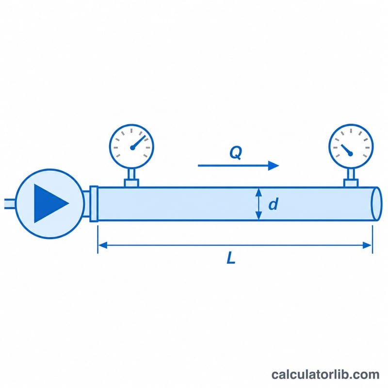
Enter the free air delivery (FAD) flow rate in litres per second, the pipe inside diameter in millimetres, the pipe length in metres and the inlet pressure in bar absolute (gauge pressure plus about 1 bar). The result shows the drop in bar and psi, the outlet pressure, the drop as a percentage of inlet pressure and the inlet air velocity.
The formula
The widely used compressed-air approximation is:
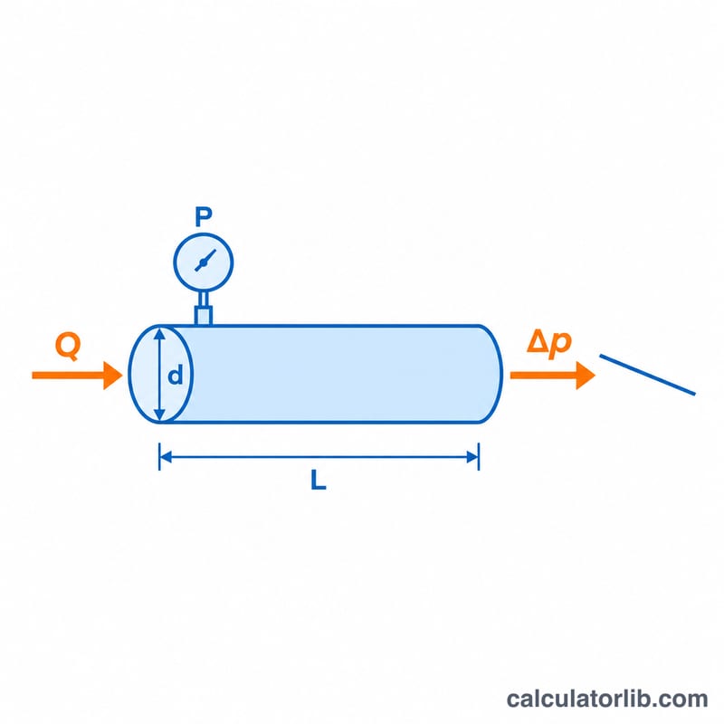
$$\Delta p = \frac{450 \, q^{1.85} \, L}{d^{5} \, p}$$where \(q\) = free air flow in l/s, \(L\) = pipe length in m, \(d\) = inside diameter in mm, \(p\) = inlet pressure in bar absolute and \(\Delta p\) = pressure drop in bar. The diameter appears to the fifth power, so a slightly larger pipe cuts losses dramatically. Fittings, valves and bends are not included; add an equivalent length for them.
Worked example
A 50 mm pipe, 100 m long, carries 100 l/s of free air at 7 bar absolute:
$$\Delta p = \frac{450 \times 100^{1.85} \times 100}{50^{5} \times 7} = \frac{450 \times 5012 \times 100}{312{,}500{,}000 \times 7} \approx 0.103\,\text{bar}$$That is about 1.5% of the inlet pressure, which is well inside the common guideline of keeping the drop in the main distribution line below about 0.1 bar.
Pressure and Flow Unit Conversions
| Quantity | Conversion |
|---|---|
| Flow | 1 l/s = 2.119 cfm = 0.06 m³/min = 3.6 m³/h |
| Pressure | 1 bar = 14.504 psi = 100 kPa |
| Gauge to absolute | bar abs = bar gauge + 1.013; psia = psig + 14.7 |
| Length | 1 mm = 0.03937 in (25 mm ≈ 0.984 in; 50 mm ≈ 1.969 in; 100 mm ≈ 3.937 in) |
| Gauge pressure | Absolute pressure (bar abs) | Gauge (psig) | Absolute (psia) |
|---|---|---|---|
| 6 bar g | 7.013 | 87.0 | 101.7 |
| 7 bar g | 8.013 | 101.5 | 116.2 |
| 8 bar g | 9.013 | 116.0 | 130.7 |
The calculator expects the inlet pressure in bar absolute, the flow as free air in l/s and the inside diameter in mm. Nominal pipe sizes (such as 2 in) differ from the true inside diameter, which depends on wall thickness and material.
Recommended Air Velocities and Pressure Drops
| Item | Commonly cited guideline |
|---|---|
| Main headers | about 6 m/s or less |
| Branch lines | about 15 m/s or less |
| Short drops, hose connections | higher velocities acceptable over short distances |
| Drop in the main line | roughly 0.1 bar |
| Total drop, compressor to point of use | no more than about 0.3–0.5 bar |
These are industry rules of thumb and not a single formal standard; the exact targets vary by manufacturer, plant and application. Compare the calculated velocity and pressure drop with them.
- If the velocity is above the guideline or the drop is above target, choose the next larger inside diameter. Because of the \(d^5\) term, this is usually very effective.
- Size for the expected future flow as well as today's flow, since the drop rises with \(Q^{1.85}\).
- Remember that bends, valves, filters, dryers and hoses add losses that this straight-pipe formula does not include.
- Every 1 bar of lost pressure forces the compressor to run at a higher set pressure, which commonly costs on the order of several percent more energy.
FAQ
What drop is acceptable?
Many guidelines suggest a total drop of no more than about 0.3 to 0.5 bar from compressor to point of use, with the main line contributing a small part.
Is the formula valid for any pipe material?
It is an engineering approximation for typical smooth industrial pipe at moderate velocities. Very rough or corroded pipes lose more pressure.
Should I use gauge or absolute pressure?
Use absolute pressure. Add about 1.013 bar to a gauge reading.