What this calculator does
This gas pipe pressure drop calculator estimates how much pressure is lost as fuel gas flows through a pipe run. It uses the low-pressure equation from the International Fuel Gas Code (IFGC), intended for systems operating below 1.5 psi, such as typical residential natural gas piping at about 7 in. w.c. or propane at 11 in. w.c. The units are US customary: cubic feet per hour, inches and feet. Always confirm the result against your local code and the appliance manufacturer data.
How to use it
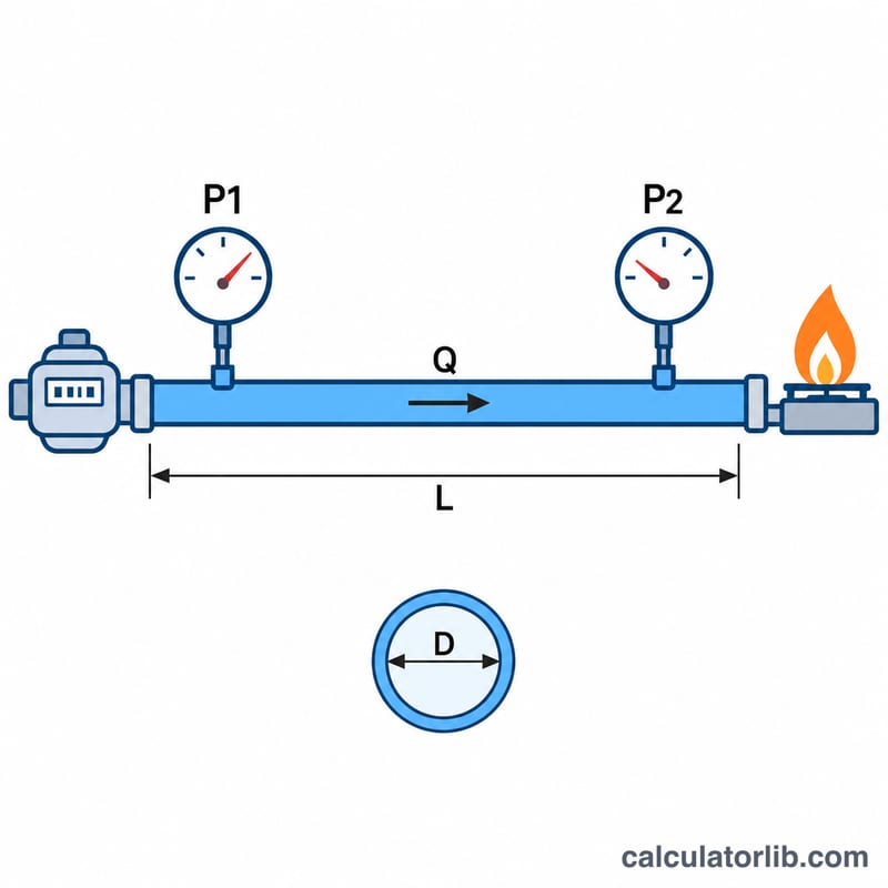
Select the gas type, enter the total flow demand in cubic feet per hour (add up all connected appliances, using their BTU ratings divided by the gas heating value), the actual inside diameter of the pipe (not the nominal size), the equivalent pipe length in feet including fittings, and the supply pressure. The calculator returns the pressure drop, the pressure at the appliance and the percentage of supply lost.
The formula explained
The IFGC solves for pipe diameter, but rearranged for pressure drop it reads:
$$\Delta H = C_r \, L \left(\frac{Q^{0.381}}{19.17\,D}\right)^{1/0.206}$$Here \(\Delta H\) is the pressure drop in inches of water column, \(Q\) is flow in cfh, \(D\) is inside diameter in inches, \(L\) is length in feet, and \(C_r\) is a gas constant: 0.6094 for natural gas and 1.2462 for undiluted propane. The strong exponent means a small increase in diameter cuts the loss dramatically.

Worked example
Natural gas, \(Q = 100\) cfh through 3/4 inch schedule 40 pipe (\(D = 0.824\) in) over \(L = 50\) ft:
$$\frac{Q^{0.381}}{19.17\,D} = \frac{5.781}{15.796} = 0.366$$$$\Delta H = 0.6094 \times 50 \times 0.366^{4.854} \approx 0.232\ \text{in. w.c.}$$With a 7 in. w.c. supply, the appliance receives about 6.77 in. w.c., a loss of roughly 3.3 percent.
Nominal Pipe Size vs. Actual Inside Diameter (Schedule 40 Steel)
The calculator needs the actual inside diameter (ID), not the nominal pipe size. The table gives standard Schedule 40 steel pipe (ASME B36.10 dimensions).
| Nominal size (in) | Actual inside diameter (in) |
|---|---|
| 1/2 | 0.622 |
| 3/4 | 0.824 |
| 1 | 1.049 |
| 1-1/4 | 1.380 |
| 1-1/2 | 1.610 |
| 2 | 2.067 |
| 2-1/2 | 2.469 |
| 3 | 3.068 |
| 4 | 4.026 |
Note: CSST (corrugated stainless steel tubing) and copper tubing have different inside diameters than Schedule 40 steel, even at the same nominal size. CSST is usually sized by its manufacturer's EHD (equivalent hydraulic diameter) rating, and copper by its tube type and wall thickness. Always check the manufacturer's data or the applicable sizing tables for those materials.
Equivalent Length of Common Fittings
Each fitting adds resistance to flow. This is commonly handled by adding an "equivalent length" of straight pipe to the measured length \(L\). The equivalent length is \(L_e = (L/D) \times D_{\text{ft}}\), where \(D_{\text{ft}}\) is the inside diameter in feet. The values below use typical threaded-fitting L/D ratios (Crane-style): 90° elbow 30, 45° elbow 16, tee run 20, tee branch 60, fully open gate valve 8. A full-port ball valve is lower, roughly 3.
| Nominal size (Sch. 40 steel) | 90° elbow (ft) | 45° elbow (ft) | Tee, run (ft) | Tee, branch (ft) | Gate valve, open (ft) |
|---|---|---|---|---|---|
| L/D ratio | 30 | 16 | 20 | 60 | 8 |
| 1/2 in | 1.6 | 0.8 | 1.0 | 3.1 | 0.4 |
| 3/4 in | 2.1 | 1.1 | 1.4 | 4.1 | 0.5 |
| 1 in | 2.6 | 1.4 | 1.7 | 5.2 | 0.7 |
| 1-1/4 in | 3.5 | 1.8 | 2.3 | 6.9 | 0.9 |
| 1-1/2 in | 4.0 | 2.1 | 2.7 | 8.1 | 1.1 |
| 2 in | 5.2 | 2.8 | 3.4 | 10.3 | 1.4 |
Example of the arithmetic: a 1 in 90° elbow is \(30 \times 1.049 / 12 \approx 2.6\) ft.
These values are approximate. Fitting losses vary by type and manufacturer. Local code, the authority having jurisdiction, and manufacturer tables (especially for CSST fittings and valves) take precedence over these figures. Add the total equivalent length of all fittings to the straight pipe length before entering \(L\).
Gas Heating Values and Constants Used
The calculator uses the low-pressure formula from the International Fuel Gas Code (IFGC, used in the United States), intended for systems below 1.5 psi. Approximate typical values:
| Item | Natural gas | Propane (undiluted) |
|---|---|---|
| Typical heating value | about 1,000 BTU/ft³ | about 2,500 BTU/ft³ |
| Constant \(C_r\) | 0.6094 | 1.2462 |
| Typical supply pressure (low pressure) | 7 in. w.c. | 11 in. w.c. |
To convert an appliance input rating to flow in cubic feet per hour (cfh):
$$\text{cfh} = \frac{ \text{BTU/h}}{ \text{heating value (BTU/ft}^3\text{)}}$$
Example: a 150,000 BTU/h appliance needs \(150{,}000 / 1{,}000 = 150\) cfh of natural gas, or \(150{,}000 / 2{,}500 = 60\) cfh of propane.
Heating values vary by gas supplier and region, so use the value from your gas utility or supplier where available. The outlet pressure is \(P_{out} = P_{supply} - \Delta P\). Appliance manufacturers specify the minimum inlet pressure required, and the local code and the authority having jurisdiction set the allowable pressure drop for the installation.
FAQ
Does this work for high-pressure gas?
No. For supply pressures above about 1.5 psi, gas compressibility matters and a high-pressure equation such as Weymouth or IGT should be used.
What length should I enter?
Use the developed length of the longest run plus an equivalent length for each elbow, tee and valve.
What drop is acceptable?
Many codes limit low-pressure systems to about 0.5 in. w.c. between the meter or regulator and the appliance, but check local requirements.