What this calculator does
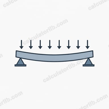
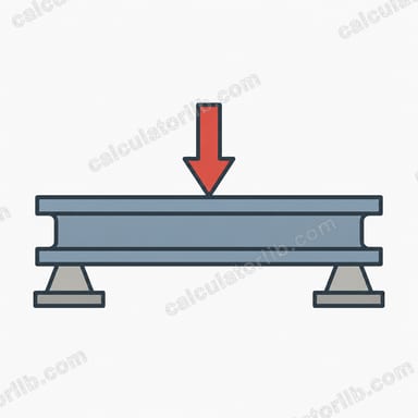
This tool estimates the maximum load an H-beam (wide-flange or I-section steel beam) can safely carry when it is simply supported at both ends. You enter the section dimensions, span, steel yield strength and a safety factor, and it returns the allowable bending moment, shear capacity, and the safe uniformly distributed load and central point load. It is intended for quick preliminary sizing, not final design.
How to use it
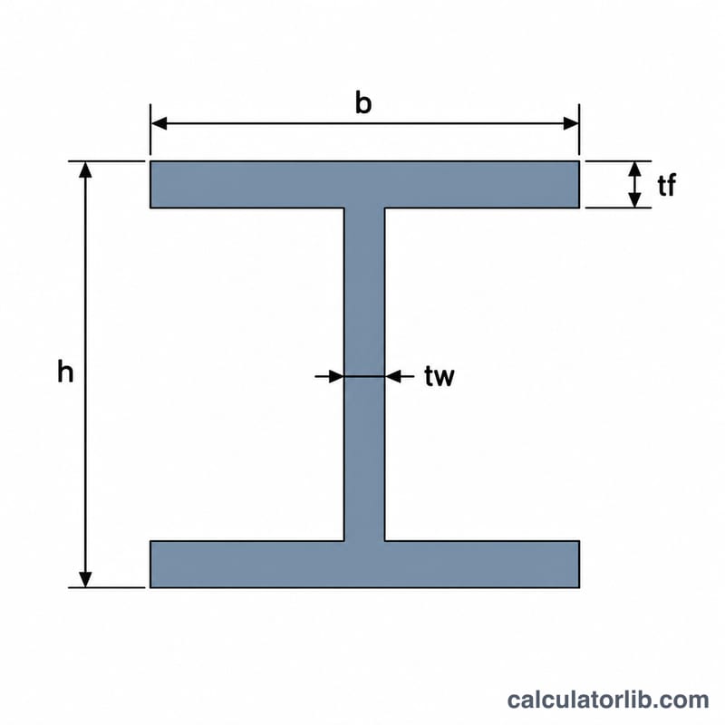
Enter overall depth \(h\), flange width \(b\), flange thickness \(t_f\) and web thickness \(t_w\) in millimetres, the span \(L\) in metres, the yield strength \(f_y\) in MPa (for example 235 to 355 for common structural steels) and a safety factor \(\gamma\) (1.5 is a typical working value). The result shows the governing load of bending or shear.
The formulas
The second moment of area of the section is:
$$I = \frac{b h^3 - (b - t_w)(h - 2t_f)^3}{12}$$The elastic section modulus is \(S = I/(h/2)\). The allowable moment and shear are:
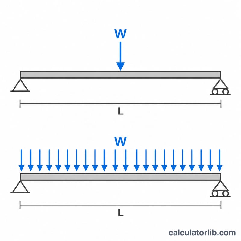
$$M_{cap} = \frac{f_y S}{\gamma}, \qquad V = \frac{0.6 f_y h t_w}{\gamma}$$For a simply supported span, the total uniform load is \(W = 8M_{cap}/L\) and the central point load is \(P = 4M_{cap}/L\). Each is capped at \(2V\) so shear can govern on short, deep spans.
Worked example
Take \(h = 200\) mm, \(b = 100\) mm, \(t_f = 10\) mm, \(t_w = 6\) mm, \(L = 4\) m, \(f_y = 250\) MPa and \(\gamma = 1.5\).
$$I = \frac{100 \times 200^3 - 94 \times 180^3}{12} = 20{,}982{,}667\,\text{mm}^4$$$$S = \frac{20{,}982{,}667}{100} = 209{,}827\,\text{mm}^3$$$$M_{cap} = \frac{250 \times 209{,}827}{1.5} = 34.97\,\text{kN}\cdot\text{m}$$$$W = \frac{8 \times 34.97}{4} = 69.94\,\text{kN}$$Shear capacity is 120 kN, so \(2V = 240\) kN and bending governs.
Typical Structural Steel Yield Strengths and Safety Factors
The calculator asks for the steel yield strength fy in MPa. The table lists nominal minimum values for thin material (about 16 mm or less) for common grades. Always confirm the grade and values on the mill certificate or in the product standard.
| Grade | Standard | Yield strength fy (MPa) | Ultimate strength fu (MPa, minimum) |
|---|---|---|---|
| S235 | EN 10025-2 | 235 | 360 |
| S275 | EN 10025-2 | 275 | 410 |
| S355 | EN 10025-2 | 355 | 470 |
| ASTM A36 | ASTM A36 (US) | 250 | 400 |
| ASTM A572 Gr. 50 | ASTM A572 (US) | 345 | 450 |
| ASTM A992 | ASTM A992 (US, wide-flange shapes) | 345 | 450 |
Notes:
- Yield strength drops as material gets thicker. For example, EN 10025 lowers the nominal fy for thicker plates and flanges. Use the value for your actual flange thickness.
- The safety factor in this calculator is a single number that divides the yield strength. It is a simplification of the partial factors used in design codes (for example γM0 = 1.0 in Eurocode 3 together with separate load factors, or the φ and Ω factors in AISC 360). A value of about 1.5 is a common simple allowable-stress style choice, but it is not a code-compliant factor.
Safe Load Comparison for Different Spans and Sections
All rows use fy = 250 MPa and a safety factor γ = 1.5, with the calculator's formulas: I = [b h³ − (b − tw)(h − 2tf)³]/12, S = I/(h/2), Mcap = fy·S/γ, W = 8M/L, P = 4M/L. Each load is capped at 2V, where V = 0.6·fy·h·tw/γ.
Section A: 200×100×6×10 mm (h × b × tw × tf). I ≈ 20,982,667 mm⁴, S ≈ 209,827 mm³, Mcap ≈ 34.97 kN·m, V = 120 kN, so 2V = 240 kN.
Section B: 300×150×6.5×9 mm. I ≈ 69,325,191 mm⁴, S ≈ 462,168 mm³, Mcap ≈ 77.03 kN·m, V = 195 kN, so 2V = 390 kN.
| Section | Span (m) | Mcap (kN·m) | Uniform load W (kN) | Central point load P (kN) | 2V cap (kN) | Governing mode |
|---|---|---|---|---|---|---|
| 200×100×6×10 | 2 | 34.97 | 139.88 | 69.94 | 240 | Bending |
| 200×100×6×10 | 4 | 34.97 | 69.94 | 34.97 | 240 | Bending |
| 200×100×6×10 | 6 | 34.97 | 46.63 | 23.31 | 240 | Bending |
| 300×150×6.5×9 | 2 | 77.03 | 308.11 | 154.06 | 390 | Bending |
| 300×150×6.5×9 | 4 | 77.03 | 154.06 | 77.03 | 390 | Bending |
| 300×150×6.5×9 | 6 | 77.03 | 102.70 | 51.35 | 390 | Bending |
Worked check (Section A, 4 m): I = (100·200³ − 94·180³)/12 = (800,000,000 − 548,208,000)/12 = 20,982,667 mm⁴. S = 20,982,667/100 = 209,827 mm³. M = 250·209,827/1.5 = 34.97 kN·m. W = 8·34.97/4 = 69.94 kN, which is below 2V = 240 kN, so bending governs.
Shear only governs on very short spans. For Section A at 1 m, 8M/L = 279.8 kN exceeds 240 kN, so W is capped at 240 kN by shear. Over 6 m, W drops by about a third relative to 4 m because capacity is inversely proportional to span.
Interpreting the Result and What It Does Not Cover
The calculator gives the lesser of the bending limit (4M/L for a central point load, 8M/L for a uniform load) and the shear limit (2V). The governing mode is whichever is smaller. On normal spans bending governs, and shear only matters for short, heavily loaded spans.
- Self-weight is included. The load W is the total the beam can carry, including its own weight. The applied load must therefore be net of the beam's self-weight, and any other permanent loads on it must be deducted too.
- Service/allowable-level value. The result comes from dividing the yield strength by one safety factor. It is not a factored ULS design resistance, so do not compare it directly with factored loads from a code load combination.
- Elastic section modulus. The formula uses the elastic modulus S, not the plastic modulus, so it ignores the extra capacity available from plastic behavior of compact sections. It is a conservative simplification.
Checks that are still required:
- Deflection: typical limits range from span/250 to span/360 for beams, and are stricter when brittle finishes such as plaster or masonry are supported. Deflection often governs on long spans before the strength limit is reached.
- Lateral-torsional buckling: if the compression flange is not braced along the span, the beam can buckle sideways at a load well below the bending limit calculated here.
- Web crippling and bearing at supports and under concentrated loads, including the need for stiffeners.
- Connections at the ends and any splices, plus local effects such as holes or notches.
The model assumes a simply supported, symmetric I or H section carrying a single point load at midspan or a uniform load. Other support conditions or load patterns need different formulas. This is general information only. A qualified structural engineer should verify any real design against the applicable code (for example Eurocode 3 or AISC 360).
FAQ
Does this check deflection or buckling? No. Deflection limits, lateral-torsional buckling of an unbraced compression flange, and web crippling can reduce the real capacity, so verify them separately.
Which axis is used? Strong-axis bending, with the load applied in the plane of the web.
Can I use this for final design? No. Use it for estimates and have a qualified structural engineer check the design against the applicable code.