What this calculator does
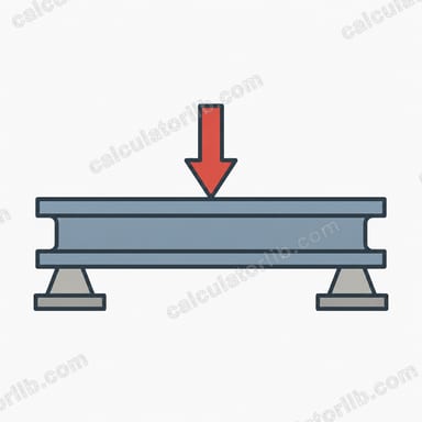
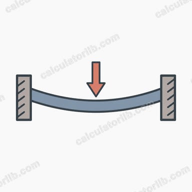
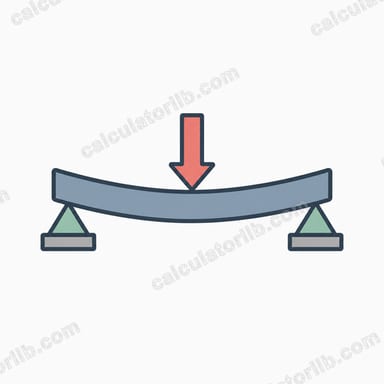
This tool computes the maximum vertical deflection of a simply supported beam (pinned at one end, roller at the other) carrying a single point load applied at mid-span. For this classic load case the largest deflection occurs directly under the load, at the center of the span, and is given by \(\delta = \frac{P L^{3}}{48 E I}\). The result is a universal structural-mechanics formula and applies regardless of country or building code — codes only affect the allowable limits you compare against.

How to use it
Enter the central point load P in newtons, the beam span L in metres, the Young's modulus E in gigapascals (steel ≈ 200 GPa, aluminium ≈ 69 GPa), and the second moment of area (moment of inertia) I in mm⁴. The calculator converts everything to consistent SI units (E to pascals, I to m⁴), applies the formula, and reports the deflection in millimetres and metres.
The formula explained
$$\delta = \frac{P \cdot L^{3}}{48 \cdot E \cdot I}$$ The deflection grows with the cube of the span, so doubling the length increases sag eightfold. Stiffer materials (higher E) and deeper sections (higher I) reduce deflection proportionally. The factor 48 in the denominator is specific to a central point load on a simply supported span.

Worked example
A steel beam with \(P = 10{,}000 \ \text{N}\), \(L = 4 \ \text{m}\), \(E = 200 \ \text{GPa} \ (2\times10^{11} \ \text{Pa})\) and \(I = 50{,}000{,}000 \ \text{mm}^4 \ (5\times10^{-5} \ \text{m}^4)\): $$\delta = \frac{10000 \times 4^{3}}{48 \times 2\times10^{11} \times 5\times10^{-5}} = \frac{640{,}000}{480{,}000{,}000} = 0.001333 \ \text{m} \approx 1.33 \ \text{mm}.$$
Typical Young's Modulus Values for Common Materials
Young's modulus (E) measures a material's stiffness in the elastic range. In the formula \(\delta = \frac{PL^3}{48EI}\), deflection is inversely proportional to E, so a material twice as stiff deflects half as much for the same section and load.
| Material | Typical E (GPa) |
|---|---|
| Structural steel | ≈ 200 |
| Stainless steel (austenitic) | ≈ 193 |
| Aluminium alloys | ≈ 69 |
| Cast iron | ≈ 100–170 |
| Titanium (common alloys) | ≈ 110 |
| Copper | ≈ 117 |
| Glass | ≈ 70 |
| Concrete | ≈ 25–35 |
| Timber (softwoods and hardwoods, along the grain) | ≈ 8–14 |
Note: these values are approximate. E varies with alloy, grade, mix design, moisture content and temperature. For design, use the value given in the material standard or the manufacturer's data sheet. Concrete and timber vary the most.
Common Deflection Limits (Span/Depth Ratios)
Serviceability limits are usually written as a fraction of the span L. The ratios below are commonly cited, and they come from model codes such as the International Building Code (IBC, Table 1604.3, United States) and from Eurocode guidance (EN 1990 and its National Annexes). Local building codes and project specifications govern, and the limits differ by country, by member type and by whether live load or total load is checked.
| Limit | Typical application | Allowable deflection for a 4 m span |
|---|---|---|
| L/480 | Members supporting sensitive finishes or equipment | 4000 / 480 ≈ 8.3 mm |
| L/360 | Floors supporting plaster or other brittle finishes (live load) | 4000 / 360 ≈ 11.1 mm |
| L/240 | General floor total load (dead + live) | 4000 / 240 ≈ 16.7 mm |
| L/180 | Roof members without a ceiling | 4000 / 180 ≈ 22.2 mm |
Example: for a 4 m (4000 mm) span with an L/360 limit, the allowable deflection is \(\frac{4000}{360} \approx 11.1\) mm. If the calculated mid-span deflection is larger, increase the moment of inertia I (a deeper section) or choose a stiffer material.
Moment of Inertia Unit Conversions
Mixed units are the most common source of error in deflection calculations. Convert every input to a consistent set of units before comparing results, and check the unit labels on the calculator form.
| Quantity | Conversion |
|---|---|
| Second moment of area | 1 cm⁴ = 10,000 mm⁴ |
| Second moment of area | 1 m⁴ = 10¹² mm⁴ |
| Second moment of area | 1 in⁴ = 416,231 mm⁴ (≈ 41.62 cm⁴) |
| Modulus | 1 GPa = 10⁹ Pa |
| Pressure / stress | 1 psi ≈ 6.895 kPa |
| Modulus | 1 Msi (10⁶ psi) ≈ 6.895 GPa |
| Force | 1 kN = 1000 N |
| Force | 1 lbf ≈ 4.448 N |
Example: steel with E = 29,000 ksi (29 Msi) converts to \(29 \times 6.895 \approx 200\) GPa, which matches the typical value for structural steel.
FAQ
Is this the maximum deflection? Yes — for a central point load on a simply supported beam the maximum deflection is at mid-span.
Does it include the beam's own weight? No, only the applied point load. Add the self-weight (a uniformly distributed load, \(\frac{5 w L^{4}}{384 E I}\)) separately if needed.
What units should I use? P in newtons, L in metres, E in GPa, I in mm⁴. The tool handles unit conversion internally and returns mm.