
What is a voltage divider?
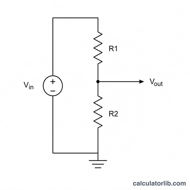
A voltage divider is one of the most fundamental circuits in electronics: two resistors in series across a source voltage. The output is tapped from the junction between the two resistors, producing a smaller, predictable fraction of the input voltage. Dividers are used to set bias points, scale sensor signals into a readable range, create reference voltages, and feed analog-to-digital converters.
How to use this calculator
Enter the input (supply) voltage Vin, the upper resistor R1 (between Vin and the output node), and the lower resistor R2 (between the output node and ground). The calculator returns the output voltage measured across R2, along with the series loop current and the total power dissipated in the resistors.
The formula explained
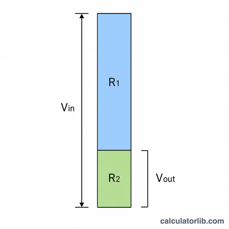
The output voltage is given by $$V_{out} = \text{Vin} \cdot \frac{\text{R2}}{\text{R1} + \text{R2}}$$ Because R1 and R2 share the same current, the voltage splits in direct proportion to resistance. The loop current is \(I = \frac{\text{Vin}}{\text{R1} + \text{R2}}\), and total power is \(P = \text{Vin} \cdot I\). Note this assumes the output is unloaded (or driving a very high-impedance input); a real load in parallel with R2 lowers Vout.
Worked example
Suppose Vin = 12 V, R1 = 1000 Ω and R2 = 2000 Ω. Total resistance is 3000 Ω, so the current is $$\frac{12}{3000} = 4\ \text{mA}$$ The output voltage is $$12 \times \frac{2000}{3000} = 8\ \text{V}$$ and total power is $$12 \times 0.004 = 48\ \text{mW}$$
FAQ
Does loading affect the output? Yes. If you connect a load resistor across R2, treat it as parallel with R2 — the effective R2 drops, lowering Vout. Choose divider resistances much smaller than the load for accuracy.
Why does lower resistance waste more power? Smaller resistors draw more current for the same voltage, so they dissipate more power. Larger resistors save power but are more sensitive to loading.
Can I solve for a resistor instead? Rearrange the formula: \(\text{R1} = \text{R2} \cdot \frac{\text{Vin} - \text{Vout}}{\text{Vout}}\) for a target Vout.