What the AC wire gauge calculator does
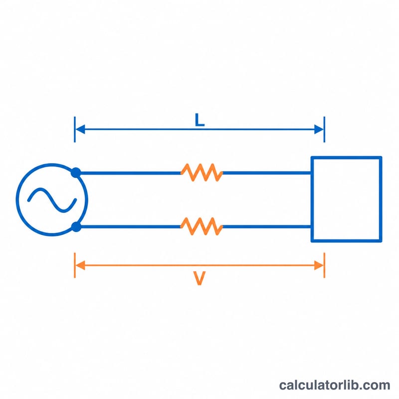
This calculator is based on US practice (American Wire Gauge and NEC 75 C ampacity values). It recommends the smallest standard conductor that carries your load current without exceeding a chosen voltage drop. Long runs often need a larger wire than ampacity alone suggests, because resistance causes voltage loss along the cable.
How to use it
Enter the load current, supply voltage, one-way distance from the panel to the load, the maximum voltage drop you accept (3% is a common design target for branch circuits), the phase and the conductor material. The tool returns the wire size, its area in circular mils, its ampacity and the real voltage drop.
The formula explained
The required area in circular mils is:
$$\text{CM} = \frac{K \times I \times L \times m}{V_d}$$Here \(K\) is the resistivity constant (12.9 for copper, 21.2 for aluminum), \(I\) is the current in amps, \(L\) is the one-way length in feet, \(m\) is 2 for single-phase (out and back) or \(\sqrt{3}\) for three-phase, and \(V_d\) is the allowed drop in volts. The calculator then picks the first AWG size whose area and ampacity are both large enough.
Worked example
A 20 A, 120 V single-phase copper circuit runs 100 ft with a 3% limit, so \(V_d = 3.6\) V.
$$\text{CM} = \frac{12.9 \times 20 \times 100 \times 2}{3.6} = 14{,}333$$10 AWG (10,380 CM) is too small, while 8 AWG (16,510 CM, 50 A) works. Its real drop is \(51{,}600 / 16{,}510 = 3.13\) V, or 2.6%.
AWG Wire Size Table: Circular Mils, Diameter and NEC 75 C Ampacity
The table lists common AWG sizes with their conductor area in circular mils (CM), the bare solid-wire diameter, and the allowable ampacity from the US National Electrical Code (NEC) Table 310.16 in the 75 °C column. These ampacities are US values and apply to not more than three current-carrying conductors in a raceway, cable or earth at 30 °C ambient. Other countries use different standards and tables. Aluminum 14 AWG is not listed in the NEC table.
| AWG | Area (CM) | Diameter (in) | Copper 75 °C (A) | Aluminum 75 °C (A) |
|---|---|---|---|---|
| 14 | 4,107 | 0.0641 | 20 | — |
| 12 | 6,530 | 0.0808 | 25 | 20 |
| 10 | 10,380 | 0.1019 | 35 | 30 |
| 8 | 16,510 | 0.1285 | 50 | 40 |
| 6 | 26,240 | 0.1620 | 65 | 50 |
| 4 | 41,740 | 0.2043 | 85 | 65 |
| 3 | 52,620 | 0.2294 | 100 | 75 |
| 2 | 66,360 | 0.2576 | 115 | 90 |
| 1 | 83,690 | 0.2893 | 130 | 100 |
| 1/0 | 105,600 | 0.3249 | 150 | 120 |
| 2/0 | 133,100 | 0.3648 | 175 | 135 |
| 3/0 | 167,800 | 0.4096 | 200 | 155 |
| 4/0 | 211,600 | 0.4600 | 230 | 180 |
Note: NEC 240.4(D) limits overcurrent protection for small copper conductors to 15 A for 14 AWG, 20 A for 12 AWG and 30 A for 10 AWG, even though the table ampacity is higher. Terminal temperature ratings (NEC 110.14) can also restrict which ampacity column applies.
Wire Size Comparison for Different Currents and Distances
Each row uses the article's formula with a 3% voltage-drop limit, where the distance is one-way length in feet, k = 12.9 for copper and 21.2 for aluminum, and m = 2 (single-phase) or √3 ≈ 1.732 (three-phase). The minimum AWG is the smallest size that satisfies both the required circular mils and the NEC 75 °C ampacity at the stated current. The actual drop is k·I·L·m divided by the chosen wire's CM, then divided by the source voltage.
| Scenario | Material | Required CM | Minimum AWG | Actual drop |
|---|---|---|---|---|
| 15 A, 120 V, 50 ft, single-phase | Copper | 5,375 | 12 AWG | 2.47% (2.96 V) |
| Aluminum | 8,833 | 10 AWG | 2.55% (3.06 V) | |
| 20 A, 120 V, 100 ft, single-phase | Copper | 14,333 | 8 AWG | 2.60% (3.13 V) |
| Aluminum | 23,556 | 6 AWG | 2.69% (3.23 V) | |
| 30 A, 240 V, 150 ft, single-phase | Copper | 16,125 | 8 AWG | 2.93% (7.03 V) |
| Aluminum | 26,500 | 4 AWG | 1.90% (4.57 V) | |
| 50 A, 208 V, 200 ft, three-phase | Copper | 35,807 | 4 AWG | 2.57% (5.35 V) |
| Aluminum | 58,845 | 2 AWG | 2.66% (5.53 V) |
Example of the arithmetic for the 30 A aluminum row: \(\text{CM}_{req} = \frac{21.2 \times 30 \times 150 \times 2}{240 \times 0.03} = \frac{190{,}800}{7.2} = 26{,}500\). Because 6 AWG is only 26,240 CM, it falls just short (3.03% drop), so 4 AWG (41,740 CM) is the next size up.
Interpreting Your Result
The recommended AWG is the larger of two sizes: the smallest wire whose circular mils meet the voltage-drop requirement, and the smallest wire whose NEC 75 °C ampacity (US, Table 310.16) meets the current. Whichever requirement is stricter determines the answer.
- Voltage-drop limits: In the US NEC, informational notes (for example in 210.19(A) and 215.2(A)) recommend about 3% maximum drop on a branch circuit and about 5% total for feeder plus branch circuit combined. These are recommendations, not mandatory rules, although other codes, specifications or equipment makers may set their own limits.
- Margin: If the actual drop shown is below your limit, the chosen wire has margin. Standard AWG sizes come in discrete steps, so the actual drop is usually somewhat lower than the limit.
- Short vs. long runs: On short runs the drop is small and ampacity usually governs the size. On long runs the drop requirement usually governs, and it can call for a size well above the ampacity minimum.
- Continuous loads: Loads expected to run for three hours or more are typically sized at 125% of the load current for conductors and overcurrent devices. If your load is continuous, enter the current multiplied by 1.25 to account for this.
- Material: Aluminum has higher resistivity (k ≈ 21.2 vs. 12.9 for copper) and lower table ampacity, so it generally needs a larger gauge for the same circuit.
This tool gives general sizing information based on simplified resistance values and the NEC 75 °C column. Temperature correction, conduit fill, terminal ratings, reactance on large conductors and local code amendments are not included, so final wire selection should follow the applicable code and be checked by a qualified electrician.
FAQ
Does it account for temperature or conduit fill?
No. It uses 75 C ampacities without derating, so apply correction factors if the wiring runs in hot or bundled conditions.
Why is distance one-way?
The formula multiplies by 2 for single-phase to cover the return conductor, so enter only the length of the run.
Is this a substitute for an electrician?
No. Use it for planning and always follow your local electrical code.