What this calculator does
Wire for a DC circuit is sized by two independent limits: ampacity (will the insulation overheat?) and voltage drop (will the load still get usable voltage?). On low-voltage systems such as 12 V or 24 V battery, solar and automotive wiring, voltage drop almost always decides the gauge long before heating does. This tool takes the current, the system voltage, the one-way distance to the load and the percentage drop you are willing to accept, then returns the smallest AWG conductor that satisfies it. Gauge sizes are the standard AWG series from 22 AWG up to 4/0 AWG.
The formula explained
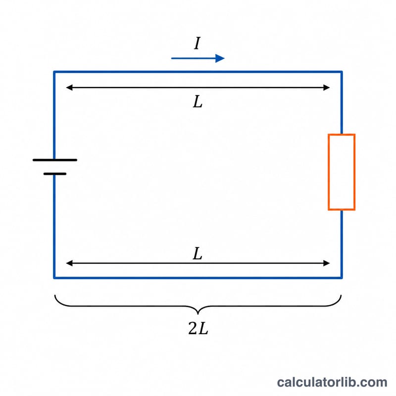
Copper and aluminum resistance is expressed as \(K\), the resistance of one foot of conductor with an area of one circular mil: \(K = 12.9\) for copper and \(K = 21.2\) for aluminum. Current travels out and back, so the length is doubled:
$$\text{CM} = \frac{2 \times K \times I \times L}{V_{d}}$$where \(I\) = current in amps, \(L\) = one-way run in feet, and \(V_{d}\) = allowed drop in volts, itself the system voltage times your percentage target. The calculator then steps up to the next real AWG size and recomputes the true drop from that conductor area.
Worked example
A 20 A load sits 10 ft from a 12 V battery and you allow a 3 % drop, so \(V_{d} = 12 \times 0.03 = 0.36\ \text{V}\). With copper:
$$\text{CM} = \frac{2 \times 12.9 \times 20 \times 10}{0.36} = 14{,}333\ \text{cmil}$$10 AWG offers only 10,380 cmil, so the answer is 8 AWG at 16,510 cmil. Its round-trip resistance is \(\frac{2 \times 12.9 \times 10}{16510} = 0.01563\ \Omega\), giving an actual drop of \(20 \times 0.01563 = 0.313\ \text{V}\), or 2.60 % — comfortably inside the target.
AWG Wire Size Table: Circular Mils and Resistance
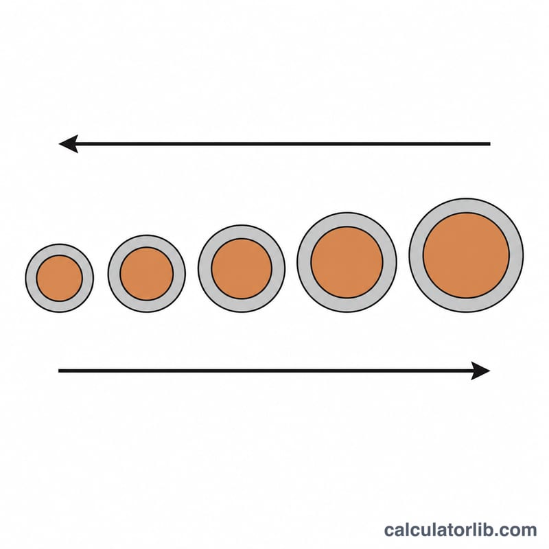
American Wire Gauge (AWG) is the conductor sizing system used in North America. Each gauge step changes the cross-sectional area by a factor of about 1.26, so three gauge steps roughly double the area and halve the resistance. The calculator works in circular mils (cmil), where one circular mil is the area of a circle 0.001 in (1 mil) in diameter, so a round conductor's area in cmil is simply its diameter in mils squared.
| AWG | Diameter (mils) | Diameter (mm) | Area (cmil) | Copper Ω / 1,000 ft @ 75 °C | Aluminum Ω / 1,000 ft @ 75 °C | Ampacity, 75 °C Cu / Al (NEC 310.16) |
|---|---|---|---|---|---|---|
| 22 | 25.3 | 0.644 | 642 | 20.1 | 33.0 | — / — |
| 20 | 32.0 | 0.812 | 1,020 | 12.6 | 20.8 | — / — |
| 18 | 40.3 | 1.024 | 1,624 | 7.94 | 13.1 | — / — (6 A as fixture wire, NEC 402.5) |
| 16 | 50.8 | 1.291 | 2,583 | 4.99 | 8.21 | — / — (8 A as fixture wire, NEC 402.5) |
| 14 | 64.1 | 1.628 | 4,107 | 3.14 | 5.16 | 20 A / — |
| 12 | 80.8 | 2.053 | 6,530 | 1.98 | 3.25 | 25 A / 20 A |
| 10 | 101.9 | 2.588 | 10,380 | 1.24 | 2.04 | 35 A / 30 A |
| 8 | 128.5 | 3.264 | 16,510 | 0.781 | 1.28 | 50 A / 40 A |
| 6 | 162.0 | 4.115 | 26,240 | 0.491 | 0.808 | 65 A / 50 A |
| 4 | 204.3 | 5.189 | 41,740 | 0.309 | 0.508 | 85 A / 65 A |
| 2 | 257.6 | 6.544 | 66,360 | 0.194 | 0.319 | 115 A / 90 A |
| 1 | 289.3 | 7.348 | 83,690 | 0.154 | 0.253 | 130 A / 100 A |
| 1/0 | 324.9 | 8.252 | 105,600 | 0.122 | 0.201 | 150 A / 120 A |
| 2/0 | 364.8 | 9.266 | 133,100 | 0.0969 | 0.159 | 175 A / 135 A |
| 3/0 | 409.6 | 10.40 | 167,800 | 0.0769 | 0.126 | 200 A / 155 A |
| 4/0 | 460.0 | 11.68 | 211,600 | 0.0610 | 0.100 | 230 A / 180 A |
How to read this table
- Areas are nominal. The cmil figures are the standard AWG values used for both solid and Class B stranded building wire. A stranded conductor is physically a little larger in overall diameter than a solid one of the same AWG because of the gaps between strands, and its resistance can be 1–3 % higher owing to the strand lay.
- The resistance columns match the constants used by this calculator. They are computed as \(R_{1000\,\text{ft}} = 1000\,K / \text{CM}\) with \(K = 12.9\) for copper and \(K = 21.2\) for aluminum (Ω·cmil/ft). Those K values correspond to conductors at roughly 75 °C — the same basis as Chapter 9, Table 8 of the US National Electrical Code — not to room temperature. At 20–25 °C copper is closer to \(K \approx 10.4\), about 20 % lower, so a size chosen with \(K = 12.9\) is deliberately conservative for a cool conductor and realistic for one running warm inside a loom, conduit or engine bay.
- Aluminum below 12 AWG is shown for completeness only. Aluminum building conductors are not used below 12 AWG in practice, and many jurisdictions restrict small aluminum branch-circuit conductors entirely.
- Ampacity is a separate limit from voltage drop. The ampacity column lists the 75 °C values of NEC Table 310.16 (a US standard) for insulated conductors in a raceway or cable, at 30 °C ambient, with no more than three current-carrying conductors. Outside the US, ampacity is taken from IEC 60364-5-52 tables or a national equivalent; vehicle and boat wiring uses SAE and ABYC ampacity tables instead, which allow more current in free air. Whichever table applies, the wire must satisfy both ampacity and voltage drop — take the larger size.
- Small-conductor overcurrent limits (US). NEC 240.4(D) generally caps overcurrent protection at 15 A for 14 AWG copper, 20 A for 12 AWG and 30 A for 10 AWG, even though the table ampacities are higher.
Interpreting Your Result
The gauge returned is the smallest standard AWG whose area is at least the required circular mils. Because real wire comes in discrete steps, the actual voltage drop reported will always be equal to or (usually) below your target — the rounding-up is in your favour. In the worked example above the target was 3 % but the installed 8 AWG delivers 2.6 %; the leftover margin is headroom for warm conductors, connector resistance and future load growth, not an error.
What the drop percentage means at the load
A 3 % drop on a 12 V system is \(12 \times 0.03 = 0.36\) V lost in the wire, leaving about 11.64 V at the device when the source is at 12.0 V. On a 24 V system the same 3 % is 0.72 V, and on 48 V it is 1.44 V — the same percentage, a very different number of volts. What that costs you depends on the load:
- Incandescent and resistive loads: power falls roughly with the square of the voltage, so a 3 % drop costs about 6 % of the heat or light output. A 10 % drop costs nearly 19 %.
- LEDs and LED drivers: a constant-current driver simply draws slightly more current to compensate and barely notices a few percent, but unregulated LED strips fed directly from 12 V dim visibly and unevenly along a long run — this is why the far end of a cheap strip looks yellow.
- Motors, pumps and compressors: low voltage means higher current for the same mechanical output, which means more heating in the motor windings and sluggish, high-current starting. Starting inrush can be several times the running current, so the momentary drop is several times the steady-state figure you calculated.
- Solar charge controllers and battery chargers: drop between the controller and the battery makes the controller see a higher voltage than the battery actually has, so it terminates absorption early and chronically undercharges the bank. Sense leads, where available, exist precisely to cancel this.
- Electronics with a minimum input voltage: check the worst case, not the nominal. A 12 V nominal lead-acid bank sits near 11.8 V when nearly discharged; subtract another 0.36 V of wiring drop and a device with a 11.5 V cutoff is on the edge.
Assumptions behind the number
- One-way distance. Enter the physical distance from source to load; the formula doubles it internally for the return conductor. Entering the round-trip length will oversize the wire by two gauge steps.
- A two-conductor DC circuit. The result is for a simple positive/negative pair. It does not apply to AC single-phase or three-phase circuits, which use different multipliers (2 and \(\sqrt{3}\) respectively) and can be affected by reactance in large conductors.
- Conductor temperature. The constants \(K = 12.9\) (copper) and \(K = 21.2\) (aluminum) Ω·cmil/ft correspond to conductors at roughly 75 °C, the conventional basis used in NEC Chapter 9, Table 8. Cool wire in open air has about 20 % less resistance than this, so real drop on a lightly loaded circuit is often better than predicted. Wire running much hotter than 75 °C — bundled, in an engine bay, in an attic — will be worse.
- Wire only. Terminals, crimps, fuse holders, relays, switches and battery posts all add resistance that no gauge calculation captures. A corroded ring terminal or a marginal crimp can easily add more drop than 20 ft of correctly sized cable.
- Resistance for the material selected. Aluminum needs roughly 1.64× the area of copper for the same drop — about two gauge steps — and requires terminations and antioxidant compound listed for aluminum.
Where the 3 % and 5 % targets come from
In the United States, the informational notes to NEC 210.19(A) (branch circuits) and 215.2(A) (feeders) suggest limiting voltage drop to 3 % on a branch circuit and 5 % total for feeder plus branch circuit for reasonable efficiency of operation. These are informational notes, not enforceable requirements, and the NEC is a US document; other countries use their own guidance (for example BS 7671 in the UK, which sets 3 % for lighting and 5 % for other uses on low-voltage installations). US recreational-marine practice under ABYC E-11 commonly uses 3 % for critical circuits such as navigation lights, bilge pumps and electronics and allows 10 % for non-critical loads. If a specific code or standard applies to your installation, follow that document rather than a generic percentage.
What this calculator does not check
Voltage drop is only one of several sizing constraints, and it is frequently not the binding one on short, high-current runs. Before you buy the wire, verify separately:
- Ampacity for the conductor at its insulation temperature rating (60/75/90 °C), from the table that applies to your installation type and country.
- Derating for ambient temperature and for more than three current-carrying conductors bundled or in a raceway — both reduce the allowable current substantially.
- Terminal temperature ratings, which commonly limit you to the 60 °C or 75 °C ampacity column even when the insulation is rated 90 °C.
- Overcurrent protection — fuse or breaker sized to protect the conductor, located close to the source of power, with an interrupting rating adequate for the available fault current. Battery banks in particular can deliver thousands of amps into a short.
- Mechanical and environmental suitability: stranding and flexibility for vibration, insulation rated for oil, UV, wet locations or direct burial, and proper support and abrasion protection.
This article is general technical information, not professional engineering advice or a substitute for the electrical code in force where you are. For permanent installations, vehicles, boats and any circuit where a failure could cause fire or injury, have the design reviewed by a licensed electrician or qualified installer.
FAQ
What voltage drop should I allow? 3 % is the usual design target for a branch circuit and 2 % for critical runs such as solar array to charge controller. Lighting and motors tolerate 5 % but lose brightness and torque.
Why is aluminum a size or two larger? Aluminum has about 64 % of the conductivity of copper, so \(K\) is 21.2 instead of 12.9 and the required area rises by the same ratio.
Does this replace an ampacity table? No. Always cross-check the chosen gauge against the ampacity rating for your insulation type, bundling and ambient temperature, and size the fuse or breaker to protect the conductor.