What this calculator does
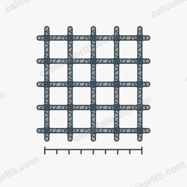
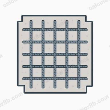
The Rebar Estimator Calculator turns the plan dimensions of a concrete slab, pad or strip footing into a practical steel take-off: how many bars run each way, how long each bar is cut, how many full stock bars to order, and the total weight of reinforcement. Bar designations and unit weights follow the US (imperial) ASTM system (#3 through #11), so sizes such as #4 mean a 1/2 inch bar weighing 0.668 lb per foot.
How to use it
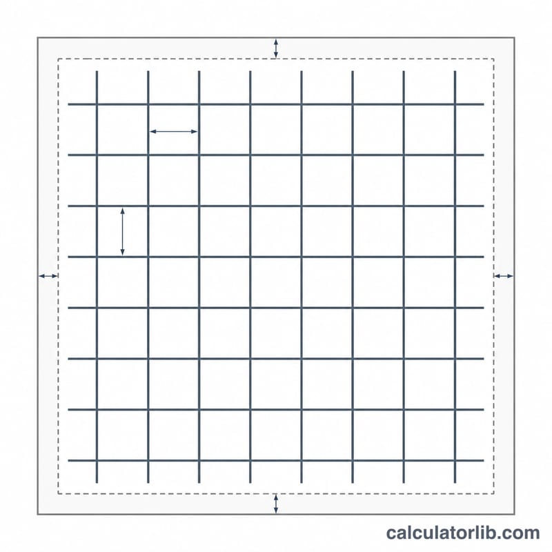
Enter the length and width of the pour in feet, choose the bar size, and give the spacing of the mat in inches (the same spacing is used both ways, which matches most slab-on-grade and footing details). Set the edge cover, the number of mats (one for a slab on grade, two for a top-and-bottom footing mat), a laps and waste allowance, and the stock bar length your supplier delivers.
The formula
Each direction gets its own bar count. With clear dimension \(D\), cover \(c\) and spacing \(s\):
$$N = \left\lfloor \frac{D - 2c}{s} \right\rfloor + 1$$Then the total weight is
$$W = \left( N_L \times L_{eff} + N_W \times W_{eff} \right) \times n \times (1 + w) \times u$$where \(L_{eff}\) and \(W_{eff}\) are the cut lengths (dimension minus two covers), \(n\) = number of mats, \(w\) = waste fraction, and \(u\) = unit weight of the bar in lb/ft.
Worked example
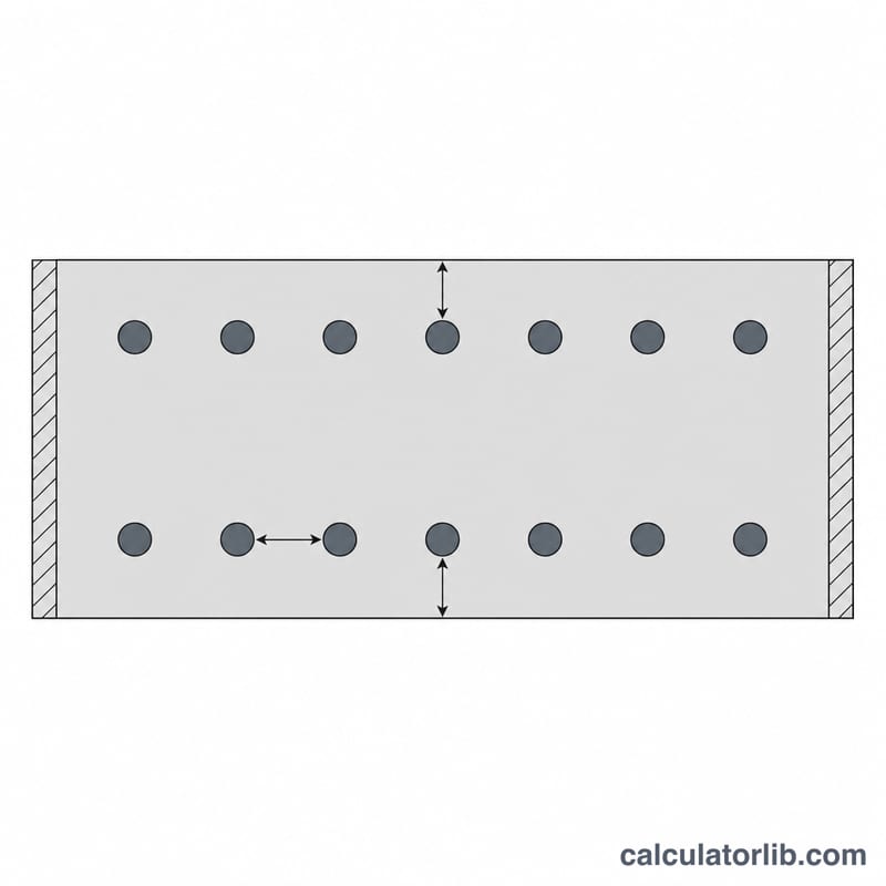
A 20 ft × 10 ft slab, #4 bar at 12 in each way, 3 in cover, one mat, 10% waste. Cover is 0.25 ft, so cut lengths are 19.5 ft and 9.5 ft, giving 10 long bars and 20 short bars:
$$\ell = (10 \times 19.5 + 20 \times 9.5) \times 1.10 = 423.5\,\text{ft}$$$$W = 423.5 \times 0.668 = 282.9\,\text{lb}$$That is 30 bars to tie and 22 twenty-foot stock bars to order.
ASTM Rebar Size and Unit Weight Table
The calculator converts total linear feet of bar into weight using the nominal unit weight of the selected bar size. These are the standard US deformed bar sizes defined in ASTM A615 (carbon steel) and ASTM A706 (low-alloy, weldable) — the imperial "#" designation used throughout this tool.
| Bar size | Soft-metric mark | Nominal diameter (in) | Nominal diameter (mm) | Area (in²) | Unit weight (lb/ft) | Unit weight (kg/m) |
|---|---|---|---|---|---|---|
| #3 | 10M | 0.375 | 9.5 | 0.11 | 0.376 | 0.560 |
| #4 | 13M | 0.500 | 12.7 | 0.20 | 0.668 | 0.994 |
| #5 | 16M | 0.625 | 15.9 | 0.31 | 1.043 | 1.552 |
| #6 | 19M | 0.750 | 19.1 | 0.44 | 1.502 | 2.235 |
| #7 | 22M | 0.875 | 22.2 | 0.60 | 2.044 | 3.042 |
| #8 | 25M | 1.000 | 25.4 | 0.79 | 2.670 | 3.973 |
| #9 | 29M | 1.128 | 28.7 | 1.00 | 3.400 | 5.060 |
| #10 | 32M | 1.270 | 32.3 | 1.27 | 4.303 | 6.404 |
| #11 | 36M | 1.410 | 35.8 | 1.56 | 5.313 | 7.907 |
Notes on reading the table:
- All figures are nominal values from ASTM A615/A706 (a United States standard). Nominal diameter and area describe a plain round bar of the same weight per foot; the deformations (ribs) are not included, so a caliper across the ribs of a #4 will read more than 0.500 in.
- The soft-metric mark is the same physical bar, not a different product. US mills have rolled soft-metric bar since the 1990s, so a bar stamped "13" is the #4 in this table. Metric sizes under other standards — for example a true 12 mm bar to EN 10080 or BS 4449 — are not interchangeable with #4, and their unit weights differ.
- Sizes #9, #10 and #11 keep the historic square-bar lineage: their areas are exactly 1.00, 1.27 and 1.56 in², which is why the diameters are not round numbers.
- kg/m is obtained from lb/ft by multiplying by 1.48816, e.g. \(0.668 \times 1.48816 = 0.994\) kg/m for a #4.
- Weight tickets from a supplier are normally billed on these nominal weights, not on a weighed bundle, so an estimate built from this table should reconcile closely with the invoice.
Typical Spacing, Cover and Stock Lengths
The inputs below are ordinary North American practice for residential and light-commercial flatwork, quoted against their sources. They are starting points for a take-off, not a design: reinforcement size, spacing, laps and cover on a real job come from the stamped structural drawings, and those govern over any value here.
| Input | Typical range | Source / basis |
|---|---|---|
| Spacing — slab-on-grade mat | 12–18 in on centre | CRSI placing practice; 18 in is common for a light #3/#4 crack-control mat |
| Spacing — footing mat | 8–12 in on centre | CRSI practice; closer spacing follows the higher steel area a footing design calls for |
| Cover — cast against and permanently exposed to earth | 3 in clear (footings, grade beams) | ACI 318 Table 20.5.1.3.1 (US) |
| Cover — formed surface exposed to earth or weather | 1.5 in clear (#5 and smaller; 2 in for #6–#18) | ACI 318 Table 20.5.1.3.1 (US) |
| Cover — interior slab, not exposed to weather or earth | 0.75 in clear (#11 and smaller) | ACI 318 Table 20.5.1.3.1 (US) |
| Bar size — slabs | #3–#5 | Common flatwork practice |
| Bar size — footings | #4–#6 | Common footing practice |
| Mats (layers) | 1 for a slab-on-grade; 2 (top and bottom) for deeper footings, grade beams and structural slabs | Design-dependent |
| Waste / cutting allowance | 5–10% for a simple rectangle; 10–15% for congested or cut-up layouts | Estimating practice |
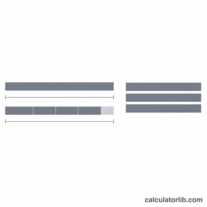
| Stock length | 20 ft is the common yard stock; 30, 40 and 60 ft available on order | Mill and distributor practice (US) |
Two cautions when you set these fields:
- The cover figures are ACI 318, a US code. Outside the United States, use the cover table in the governing code — Eurocode 2 (EN 1992-1-1), CSA A23.1 in Canada, AS 3600 in Australia and so on — which sets cover from exposure class and can differ substantially from these values.
- Cover reduces the bar grid, not just the edge. This calculator subtracts cover from both ends of each dimension, so a 20 ft footing with 3 in cover is reinforced over 19.5 ft. The result is a bar-grid length, not a cut list with hooks, bends or laps.
Turning the Estimate Into an Order
The output of this tool is a clean rectangular grid: bar counts each way, linear feet, stock pieces and weight. A purchase order is that number plus several allowances the grid math does not contain. Work through the list below before you send the quantity to a supplier.
Worked example
A 20 ft × 24 ft slab, #4 bar at 16 in on centre, 3 in cover, one mat, 10% waste, 20 ft stock:
Effective grid after cover: \(L_e = 20 - \frac{2 \times 3}{12} = 19.5\) ft and \(W_e = 24 - \frac{2 \times 3}{12} = 23.5\) ft, with spacing \(s = \frac{16}{12} = 1.3333\) ft.
$$N_L = \left\lfloor \frac{23.5}{1.3333} \right\rfloor + 1 = 17 + 1 = 18 \quad\text{bars at } 19.5 \text{ ft}$$
$$N_W = \left\lfloor \frac{19.5}{1.3333} \right\rfloor + 1 = 14 + 1 = 15 \quad\text{bars at } 23.5 \text{ ft}$$
$$18 \times 19.5 + 15 \times 23.5 = 351 + 352.5 = 703.5 \text{ ft}$$
With 10% waste that is \(703.5 \times 1.10 = 773.85\) ft, and at 0.668 lb/ft the steel weighs 516.93 lb (about 234 kg). At 20 ft stock that is \(773.85 \div 20 = 38.7\), so 39 bars — and most yards sell #4 in bundles, so you will likely take 40.
Before you order
- Round up twice. Once to whole bars, then again to the supplier's bundle quantity. Partial bundles are often priced at a premium or refused outright.
- Add laps explicitly. A waste percentage covers offcuts, not splices. Use the lap length on the drawings — commonly 40–60 bar diameters in US practice, so roughly 20–30 in for a #4 — and add one lap length for every splice you will actually make. On any run longer than the stock length, every bar in that direction needs at least one lap.
- Add the items the grid ignores. Corner bars and L-bars at footing intersections, dowels into walls and columns, chairs or bolsters (roughly one per 3–4 ft of bar, more on soft subgrade), bar supports under a top mat, and tie wire at roughly 1 lb per 100 intersections. None of these appear in the bar-grid weight.
- Check the last spacing. Because the bar count is a floor plus one, the final gap is usually smaller than the nominal spacing — which is fine. What is not fine is tightening the count to "make it even" in a way that pushes a gap above the specified spacing. If the remainder is awkward, reduce spacing slightly and add a bar; never stretch it.
- Confirm the long stock is deliverable. 40 ft and 60 ft bar saves splices but needs a flatbed, turning room and a place to lay it down. Verify truck access and site storage before specifying anything longer than 20 ft, and confirm who is cutting and bending.
- Reconcile with the drawings. Check the final quantity against the stamped structural drawings and the fabricator's bar bending schedule. Where they disagree with this estimate, the drawings and the schedule win.
This section describes general construction-estimating practice and is not engineering advice. Reinforcement design, cover, lap lengths and detailing must come from the licensed design professional and the code in force at the project location.
FAQ
Why add a waste allowance? Lap splices, corner bars, dowels and off-cuts all consume steel that the plain grid math ignores. 5-10% is typical on simple work; congested or heavily spliced layouts can run higher.
Does it work for a footing? Yes - enter the footing as a long, narrow rectangle. The cross bars then become your transverse ties at the chosen spacing.
Is the result a buy list? Treat it as a budget and check quantity. The stamped structural drawings, the engineer lap lengths and the bender schedule always govern the final order.