What this calculator does
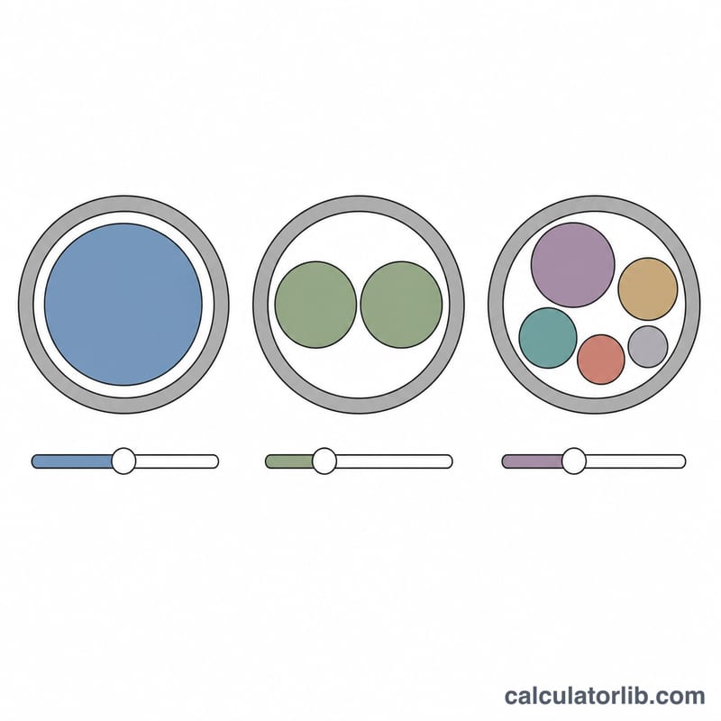
This tool applies United States National Electrical Code (NEC) Chapter 9 conduit fill rules, using Table 1 percentage limits, Table 4 interior areas for EMT, PVC Schedule 40 and RMC, and Table 5 approximate areas for THHN/THWN-2 conductors. It is written for the US code basis; outside the United States use your own national wiring regulations. It is built for real raceways, where a run rarely carries one gauge: you can mix up to three different wire sizes with their own counts, for example four 10 AWG circuit conductors plus two 12 AWG travellers.
How to use it
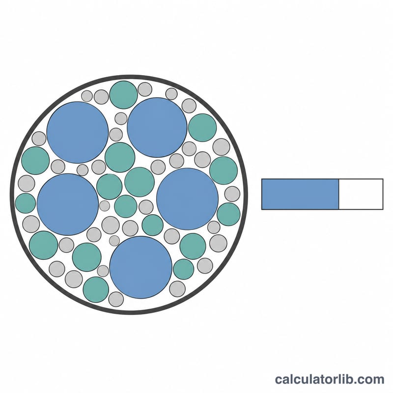
Choose the conduit type and trade size, then enter each wire gauge and how many of that gauge are in the raceway. Grounding and neutral conductors count as conductors for fill, so include them. The result shows the fill percentage, the code limit that applies to your conductor count, and the remaining usable area in square inches so you can judge whether another circuit will fit.
The formula explained
Fill is a pure area ratio. With \(n_i\) = number of wires of gauge \(i\), \(A_i\) = area of one such wire in square inches, and \(A_c\) = conduit interior area:
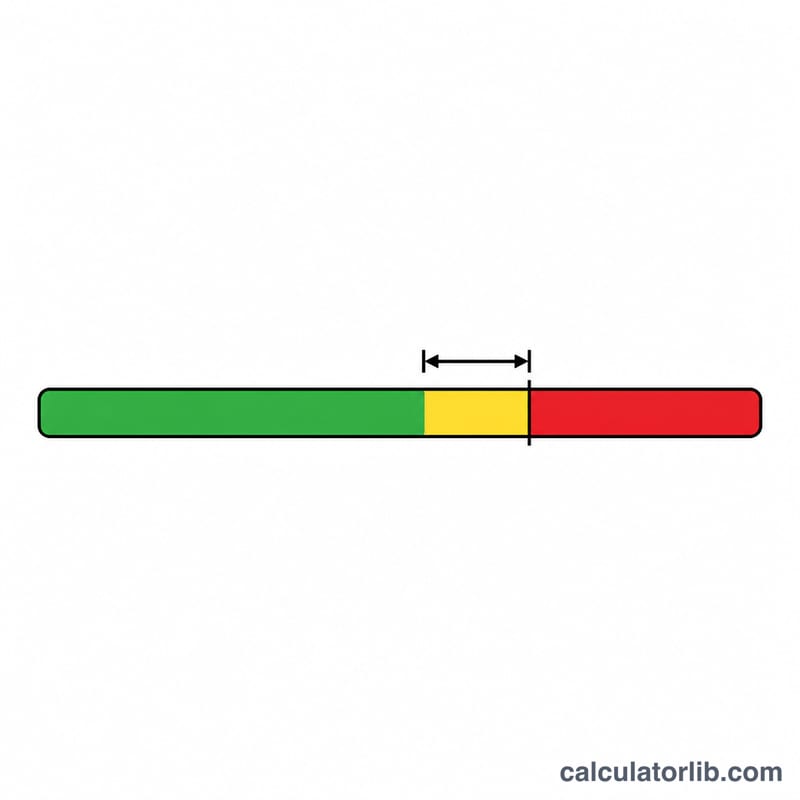
$$\text{Fill} = \frac{\sum_{i} n_i A_i}{A_c} \times 100$$The limit is not fixed: it is 53% for a single conductor, 31% for exactly two, and 40% for three or more, because pulling friction and heat behave differently in each case.
Worked example
Take 1/2 in EMT (\(A_c = 0.304\) sq in) with four 10 AWG THHN (0.0211 sq in each) and two 12 AWG THHN (0.0133 sq in each). Six conductors, so the limit is 40%.
$$\text{Fill} = \frac{4 \times 0.0211 + 2 \times 0.0133}{0.304} \times 100 = \frac{0.111}{0.304} \times 100 = 36.51\%$$The allowable area is \(0.304 \times 0.40 = 0.1216\) sq in, leaving 0.0106 sq in spare. The pull passes, but barely.
NEC Conduit Areas and Conductor Areas
The two tables below hold the data this calculator uses. They come from the United States National Electrical Code (NFPA 70), Chapter 9 — Table 4 for raceway areas and Table 5 for conductor areas. These are US values; installations under other national codes (for example CSA C22.1 in Canada or IEC-based rules elsewhere) use different tables and different fill limits.
Table 4 — Interior area and allowable fill area (square inches)
The percentage columns are the maximum conductor area permitted by Chapter 9, Table 1: 53% for one conductor, 31% for exactly two, and 40% for three or more.
| Trade size (in) | Type | Total interior area | 53% (1 cond.) | 31% (2 cond.) | 40% (3+ cond.) |
|---|---|---|---|---|---|
| 1/2 | EMT | 0.304 | 0.161 | 0.094 | 0.122 |
| 1/2 | PVC Sch 40 | 0.285 | 0.151 | 0.088 | 0.114 |
| 1/2 | RMC | 0.314 | 0.166 | 0.097 | 0.125 |
| 3/4 | EMT | 0.533 | 0.283 | 0.165 | 0.213 |
| 3/4 | PVC Sch 40 | 0.508 | 0.269 | 0.157 | 0.203 |
| 3/4 | RMC | 0.549 | 0.291 | 0.170 | 0.220 |
| 1 | EMT | 0.864 | 0.458 | 0.268 | 0.346 |
| 1 | PVC Sch 40 | 0.832 | 0.441 | 0.258 | 0.333 |
| 1 | RMC | 0.887 | 0.470 | 0.275 | 0.355 |
| 1-1/4 | EMT | 1.496 | 0.793 | 0.464 | 0.598 |
| 1-1/4 | PVC Sch 40 | 1.453 | 0.770 | 0.450 | 0.581 |
| 1-1/4 | RMC | 1.526 | 0.809 | 0.473 | 0.610 |
| 1-1/2 | EMT | 2.036 | 1.079 | 0.631 | 0.814 |
| 1-1/2 | PVC Sch 40 | 1.986 | 1.052 | 0.616 | 0.794 |
| 1-1/2 | RMC | 2.071 | 1.098 | 0.642 | 0.829 |
| 2 | EMT | 3.356 | 1.778 | 1.040 | 1.342 |
| 2 | PVC Sch 40 | 3.291 | 1.744 | 1.020 | 1.316 |
| 2 | RMC | 3.408 | 1.806 | 1.056 | 1.363 |
Each total area is simply the circle area of the raceway's actual internal diameter, which is why EMT, PVC Schedule 40 and RMC of the same trade size differ. For 1 in EMT (internal diameter 1.049 in):
$$A_c=\frac{\pi}{4}d^2=\frac{\pi}{4}\,(1.049\ \text{in})^2=0.864\ \text{in}^2$$Table 5 — Approximate area per conductor, THHN/THWN-2 (square inches)
| Size (AWG) | Area per conductor |
|---|---|
| 14 | 0.0097 |
| 12 | 0.0133 |
| 10 | 0.0211 |
| 8 | 0.0366 |
| 6 | 0.0507 |
| 4 | 0.0824 |
| 2 | 0.1158 |
| 1/0 | 0.1855 |
These areas are for THHN/THWN-2 insulation only. Other insulation types in Chapter 9, Table 5 have different overall diameters and therefore different areas — XHHW and RHH/RHW, for example, are larger at the same copper size, so substituting an insulation type without re-checking the area can push a run over the limit even though the AWG size and conductor count are unchanged. For bare conductors, use Chapter 9, Table 8.
Interpreting Your Fill Percentage
The calculator reports one headline number: the share of the raceway's interior cross-section occupied by your conductors.
$$\text{Fill}=\frac{A_w}{A_c}\times 100\%$$Compare it to the limit that applies to your total conductor count \(N\) under US NEC Chapter 9, Table 1: 53% when \(N=1\), 31% when \(N=2\), and 40% when \(N\ge 3\). The 31% figure for two conductors is not a typo — two circles pack poorly inside a third, so the Code is stricter there than for a single conductor or for a bundle.
A worked example
Six 12 AWG THHN plus three 10 AWG THHN in 1 in EMT:
$$A_w=6\,(0.0133)+3\,(0.0211)=0.0798+0.0633=0.1431\ \text{in}^2$$$$\text{Fill}=\frac{0.1431}{0.864}\times100\%=16.6\%$$With \(N=9\) conductors the limit is 40%, so a fill of 16.6% passes with a wide margin. The headroom is what tells you how much more will fit:
$$A_{\text{head}}=0.40\,(0.864)-0.1431=0.346-0.1431=0.203\ \text{in}^2$$That 0.203 in² would accept, for instance, two more 1/0 AWG THHN at 0.1855 in² each? No — two would need 0.371 in². One would fit; a second would not. Dividing the headroom by the area of the conductor you are considering is the quickest way to answer "can I add one more?"
What a passing result does and does not tell you
Fill is purely a geometric area test from Chapter 9. Passing it means the conductors physically fit within the Code's packing allowance. It says nothing about heat, voltage drop, pulling tension, or whether the run is physically pullable. Several independent checks remain:
- Ampacity adjustment — 310.15(C)(1). Where more than three current-carrying conductors are bundled in a raceway, each conductor's allowable ampacity must be reduced by the adjustment factors (80% for 4–6 conductors, 70% for 7–9, 50% for 10–20, and so on). Neutrals that carry only unbalanced current and equipment grounding conductors are generally not counted as current-carrying. A raceway at 20% fill can still be a Code violation if the derated ampacity falls below the load or the overcurrent device rating.
- Grounding conductors count toward fill. The Notes to the Chapter 9 tables require equipment grounding and bonding conductors to be included in the fill calculation even though they are not current-carrying for ampacity purposes. Enter them as one of the wire rows.
- Rounding. The Notes to the Chapter 9 tables permit the next higher whole number of conductors where the calculation produces a decimal of 0.8 or larger. Conduit trade sizes themselves are not interpolated — if the required area lands between two sizes, you go up to the next manufactured trade size. Short nipples not exceeding 24 in between enclosures are separately permitted to be filled to 60%.
- Bends — 360 degrees per run. No more than the equivalent of four quarter bends (360 degrees total) are permitted between pull points: 358.26 for EMT, 352.26 for PVC, 344.26 for RMC. A run at legal fill with 450 degrees of bend is still non-compliant, and in practice will be very hard to pull.
If you exceed the limit
There is no allowance for "slightly over." The remedies are to step up to the next larger trade size, to split the conductors across two or more raceways (remembering that splitting also reduces the bundle count and so may relieve ampacity derating), to switch to a raceway type with a larger interior area at the same trade size (RMC is roomier than PVC Schedule 40 at every size in the table above), or to re-examine whether every conductor in the bundle actually needs to share that raceway.
Practical note: even a compliant fill in the 35–40% range with many large conductors and multiple bends can be difficult to pull without damaging insulation. Many installers deliberately target a lower fill on long or heavily bent runs, and on runs they expect to add circuits to later. This article is general reference information about the US NEC; the Code as adopted and amended in your jurisdiction, and the authority having jurisdiction, govern the actual installation.
Key Terms and Definitions
- Raceway — an enclosed channel of metal or non-metallic material designed expressly to hold wires, cables or busbars. Conduit and tubing are raceways; so are wireways and surface raceways.
- Trade size — the nominal designation of a conduit (1/2, 3/4, 1 in and so on). It is a name, not a measurement: 1 in EMT has an actual internal diameter of 1.049 in, and 1 in RMC has 1.063 in. Always use the Chapter 9, Table 4 area for the specific raceway type rather than computing from the trade size.
- EMT (electrical metallic tubing) — thin-wall steel or aluminum tubing, unthreaded, joined with set-screw or compression fittings. Article 358 of the US NEC. The lightest and most common of the three types here.
- PVC Schedule 40 — rigid non-metallic conduit, Article 352, in the Schedule 40 wall thickness. Non-conductive, so a separate equipment grounding conductor is required in the raceway. Its thicker wall gives it the smallest interior area of the three types at most trade sizes.
- RMC (rigid metal conduit) — heavy-wall threaded steel or aluminum conduit, Article 344. The strongest option, and the one with the largest interior area at a given trade size.
- THHN / THWN-2 — the common thermoplastic-insulated (PVC with a nylon jacket) building wire in US installations. THHN is rated 90 °C dry; THWN-2 is rated 90 °C wet and dry; most building wire is dual-rated THHN/THWN-2. Its slim nylon-jacketed profile makes it the smallest-area option in Chapter 9, Table 5 for most sizes.
- Conductor — any single wire, insulated or bare, in the raceway. Every conductor counts toward the fill area, including grounds.
- Current-carrying conductor — a subset of the above, used only for ampacity adjustment under 310.15(C)(1). Phase (ungrounded) conductors always count; a neutral carrying only the unbalanced current of a balanced 3-wire or 4-wire system generally does not; equipment grounding conductors do not.
- Equipment grounding conductor (EGC) — the conductor that bonds metal equipment enclosures back to the system ground to provide a fault-current path. Included in fill, excluded from ampacity adjustment.
- Neutral (grounded conductor) — the circuit conductor intentionally connected to earth at the service, which carries return current under normal operation. Always included in fill; counted for ampacity adjustment only in the cases the Code specifies (for example the neutral of a 3-wire circuit from a 4-wire, 3-phase, wye system).
- AWG (American Wire Gauge) — the US sizing scale for conductors. Numbers run down as wire gets bigger (14 is small, 2 is large), and continue past 1 into 1/0, 2/0, 3/0, 4/0 ("one aught" and up), after which sizes are given in thousands of circular mils (kcmil).
- Cross-sectional area — the area of the circle the conductor occupies, insulation included. Conductor areas come from Chapter 9, Table 5 and are insulation-specific; they are larger than the bare copper area.
- Fill percent — total conductor area divided by the raceway's total interior area, expressed as a percentage.
- Allowable fill area — the interior area multiplied by the applicable Table 1 percentage (53%, 31% or 40%). This is the number in square inches your conductor area must not exceed.
- Headroom — allowable fill area minus conductor area used, in square inches. Divide it by the Table 5 area of a candidate conductor to see how many more of that size the raceway can legally take.
FAQ
Do ground wires count? Yes. Every conductor in the raceway, including equipment grounding and neutral conductors, contributes its area.
Why does a single wire get 53%? One conductor has no bundle friction and cools more freely, so the code allows more of the interior area than for a crowded raceway.
Does passing fill mean the design is compliant? No. Fill is one test only. You still need ampacity adjustment for more than three current-carrying conductors, correct conductor sizing, bend and pull-box limits, and any local amendments.