What this calculator does (United Kingdom)
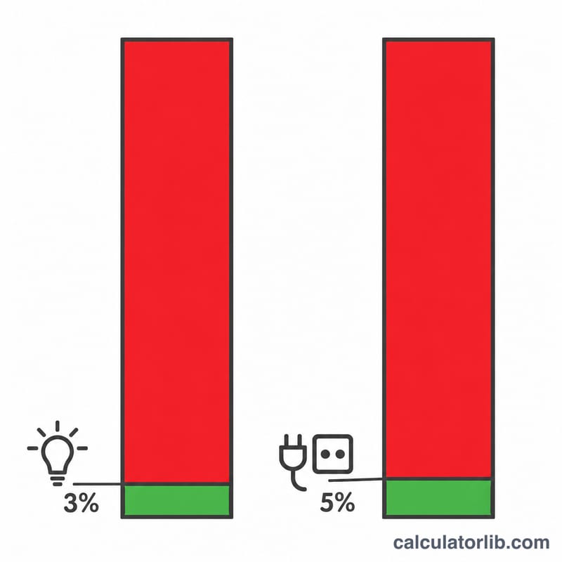
This tool applies the United Kingdom wiring regulations, BS 7671, and its Appendix 4 tabulated mV/A/m values for 70 °C thermoplastic insulated copper cables. It assumes a nominal supply of 230 V single-phase or 400 V three-phase and the standard permitted drops of 3% for lighting circuits and 5% for all other uses, measured from the origin of the installation to the point of use. It is not valid for installations outside the UK and Ireland, where nominal voltages and permitted drops differ.
How to use it
Pick your supply type, choose the live conductor cross-sectional area, then enter the design current \(I_b\) in amperes and the route length \(L\) in metres — the actual cable run, not the straight-line distance. Finally select whether the circuit feeds lighting or other loads so the correct limit is applied.
The formula explained
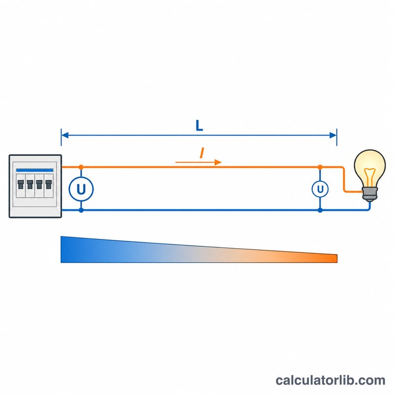
Voltage drop is calculated from the tabulated millivolts of drop per ampere per metre of route:
$$\Delta V = \frac{(\text{mV/A/m}) \times I_b \times L}{1000}$$Here \(I_b\) = design current in amperes, \(L\) = route length in metres, and the mV/A/m figure already accounts for the two (or three) current-carrying conductors and the \(\sqrt{3}\) factor in a three-phase cable. The result as a percentage is \(\%\Delta V = \frac{\Delta V}{U_0} \times 100\), with \(U_0\) the nominal voltage.
Worked example
A 230 V ring final circuit in 2.5 mm² twin and earth, 20 A design current, 15 m route. The tabulated value is 18 mV/A/m:
$$\Delta V = \frac{18 \times 20 \times 15}{1000} = 5.4\,\text{V}$$$$\%\Delta V = \frac{5.4}{230} \times 100 = 2.35\%$$The 5% limit allows 11.5 V, so the circuit passes with 6.1 V of headroom and could run up to about 31.9 m at that current.
BS 7671 Appendix 4 Voltage Drop Values (mV/A/m)
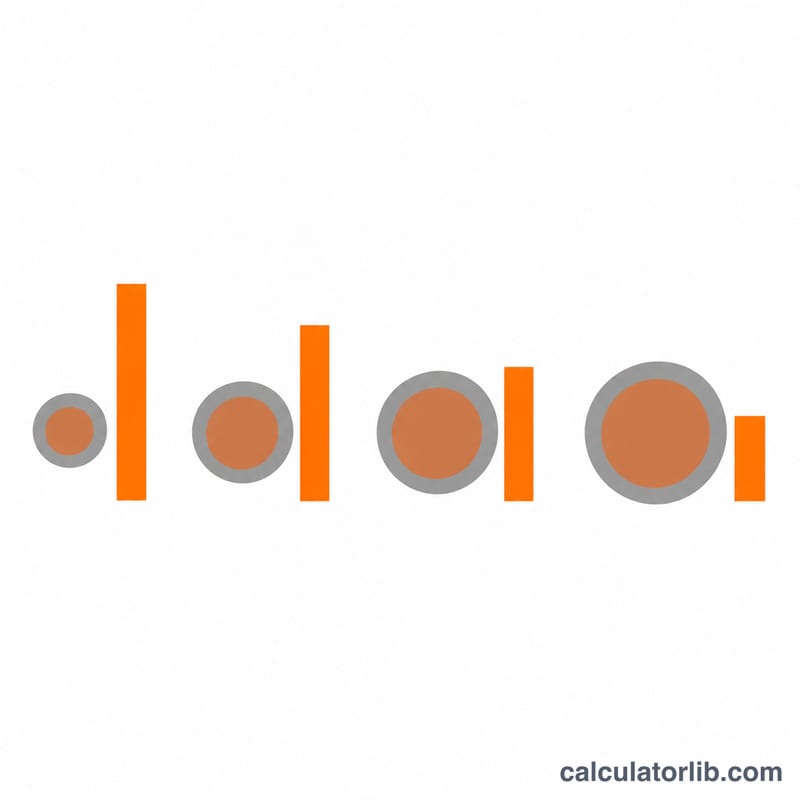
Voltage drop in the UK is not calculated from first-principles resistivity on site — it is looked up. BS 7671 (the IET Wiring Regulations, the UK national standard for electrical installations) publishes a tabulated voltage drop figure in millivolts per ampere per metre (mV/A/m) for each conductor size and cable construction in its Appendix 4 tables. That single number already accounts for the resistance of both the line and the return conductor, so you never double the route length.
The figures below are the commonly quoted Appendix 4 reference values for 70 °C thermoplastic (PVC) insulated copper conductors — the construction used for most UK twin-and-earth (6242Y/6243Y) and PVC singles installations. They are stated at the conductor's full permitted operating temperature of 70 °C, which is the conservative (worst-case) condition; a lightly loaded cable running cooler will drop slightly less.
| Live conductor CSA (mm²) | Single-phase, two-core (mV/A/m) | Balanced three-phase, three/four-core (mV/A/m) |
|---|---|---|
| 1.0 | 44 | 38 |
| 1.5 | 29 | 25 |
| 2.5 | 18 | 15 |
| 4 | 11 | 9.5 |
| 6 | 7.3 | 6.4 |
| 10 | 4.4 | 3.8 |
| 16 | 2.8 | 2.4 |
| 25 | 1.75 | 1.50 |
| 35 | 1.25 | 1.10 |
| 50 | 0.93 | 0.80 |
Why the three-phase column is smaller
A single-phase figure is the drop across the loop of line plus neutral, referred to the 230 V line-to-neutral voltage. A balanced three-phase figure is referred to the 400 V line-to-line voltage, where the geometry contributes a factor of \(\sqrt{3}/2 \approx 0.866\):
$$m_{3\phi} \approx 0.87 \times m_{1\phi}$$So 6 mm² gives \(0.87 \times 7.3 \approx 6.4\) mV/A/m. Because the three-phase drop is also compared against a larger permitted voltage (5% of 400 V = 20 V rather than 5% of 230 V = 11.5 V), a three-phase submain will almost always run much further than a single-phase one of the same cable size.
Larger sizes split into r, x and z
At 25 mm² and above, conductor reactance stops being negligible and Appendix 4 publishes three columns instead of one: \((mV/A/m)_r\) the resistive component, \((mV/A/m)_x\) the reactive component, and \((mV/A/m)_z\) the impedance figure, where
$$z = \sqrt{r^2 + x^2}$$The 25–50 mm² values in the table above are the resistive components; the corresponding \(z\) figures are only marginally higher (for 50 mm² two-core, roughly 0.94 against 0.93), but for larger cables, long runs and power-factor-sensitive loads the standard's own \(r\), \(x\) and \(z\) columns must be used rather than a single rule-of-thumb number. The same applies to the 70 mm² and 95 mm² options in this calculator.
Please confirm before you rely on these. These are reference values for a 70 °C PVC copper cable and are reproduced here for checking and estimating only. Values differ for 90 °C thermosetting (XLPE) insulation, for aluminium conductors, for armoured (SWA) and mineral-insulated cables, and for flat twin cable installed in thermal insulation. Always verify the mV/A/m figure against the current edition of BS 7671 Appendix 4 and against the cable manufacturer's published data for the exact cable and installation method you are using, and note that BS 7671 is the UK standard — other countries apply different tables and different permitted limits.
Voltage Drop Across Typical UK Circuits
BS 7671 limits voltage drop between the origin of the installation and the point of use, for an installation supplied from a public low-voltage distribution network, to 3% for lighting and 5% for other uses. At the UK single-phase nominal of 230 V that is 6.9 V and 11.5 V; on a 400 V three-phase supply it is 12 V and 20 V. Every row below is computed as
$$V_d = \frac{m \, I_b \, L}{1000}, \qquad \%V_d = \frac{V_d}{U} \times 100$$| Circuit | Supply | Size (mm²) | mV/A/m | \(I_b\) (A) | Length (m) | Limit | Drop (V) | Drop (%) | Verdict |
|---|---|---|---|---|---|---|---|---|---|
| Domestic lighting circuit | 230 V 1-ph | 1.5 | 29 | 6 | 20 | 3% = 6.9 V | 3.48 | 1.51% | Pass |
| Ring final (sockets) | 230 V 1-ph | 2.5 | 18 | 20 | 15 | 5% = 11.5 V | 5.40 | 2.35% | Pass |
| Radial socket circuit | 230 V 1-ph | 4 | 11 | 27 | 25 | 5% = 11.5 V | 7.43 | 3.23% | Pass |
| 9.5 kW electric shower | 230 V 1-ph | 10 | 4.4 | 40 | 18 | 5% = 11.5 V | 3.17 | 1.38% | Pass |
| Garden outbuilding submain | 230 V 1-ph | 6 | 7.3 | 32 | 40 | 5% = 11.5 V | 9.34 | 4.06% | Pass (tight) |
| Three-phase submain | 400 V 3-ph | 16 | 2.4 | 63 | 60 | 5% = 20 V | 9.07 | 2.27% | Pass |
Worked check — the 4 mm² radial
Substituting the 4 mm² two-core figure of 11 mV/A/m, a design current of 27 A and a 25 m route length:
$$V_d = \frac{11 \times 27 \times 25}{1000} = \frac{7425}{1000} = 7.425\ \text{V}$$$$\%V_d = \frac{7.425}{230} \times 100 = 3.23\%$$Against the 5% allowance of \(230 \times 0.05 = 11.5\) V, there is 4.08 V of headroom — the circuit could be extended to about 38 m on the same cable before the limit is reached.
Reading the results
- Length dominates. The shower draws 40 A — more than any other single-phase circuit here — yet drops only 1.38%, because 10 mm² cable and an 18 m run are both working in its favour. The 32 A outbuilding submain at 40 m drops three times as much.
- Long submains are the usual failure. The 6 mm² garden run at 4.06% passes, but add 10 m of trench or uprate the load and it fails. Outbuildings, detached garages and EV chargers are the circuits where 10 mm² or 16 mm² is normally needed for volt drop rather than for current-carrying capacity.
- Lighting is held to a tighter limit on a smaller base. 3% of 230 V is only 6.9 V, so a 1.5 mm² lighting circuit at 6 A reaches it at roughly 39 m of route length.
- Ring finals are conservative here. A true ring final circuit shares current between two legs, so the real drop is lower than this radial calculation. Treating it as a radial, as above, errs on the safe side.
Scope and caveats. The limits and mV/A/m values used here are those of BS 7671 as applied in the UK, with nominal voltages of 230 V single-phase and 400 V three-phase; other countries use different limits and different tabulated data. Voltage drop is only one of several checks a circuit must pass — current-carrying capacity after derating, protective device coordination, earth fault loop impedance and disconnection times must all be verified separately. This calculator is a design aid for estimating and sanity-checking, not a substitute for a full design and certification by a competent person.
FAQ
Why is three-phase drop lower for the same cable? Line-to-line voltage drop in a balanced three-phase circuit is roughly \(\sqrt{3}/2\) of the single-phase value, and the 400 V base makes the percentage smaller still.
Can I correct for a cooler conductor? Yes. The tabulated figures assume the conductor is at full operating temperature, so a lightly loaded cable drops less; Appendix 4 gives a correction factor that this calculator deliberately omits so results stay conservative.
What if the circuit fails? Increase the conductor size, shorten the route, reduce the load, or move the distribution board closer to the load.