What Is the 3 Phase Voltage Drop Calculator?
This tool estimates the voltage lost along a balanced three-phase cable run. Excessive voltage drop causes dim lighting, overheating, nuisance tripping and poor motor performance, so most installation standards limit it to around 3–5% of nominal voltage. The calculator works in metric units and applies to any balanced three-phase AC circuit.
The Formula
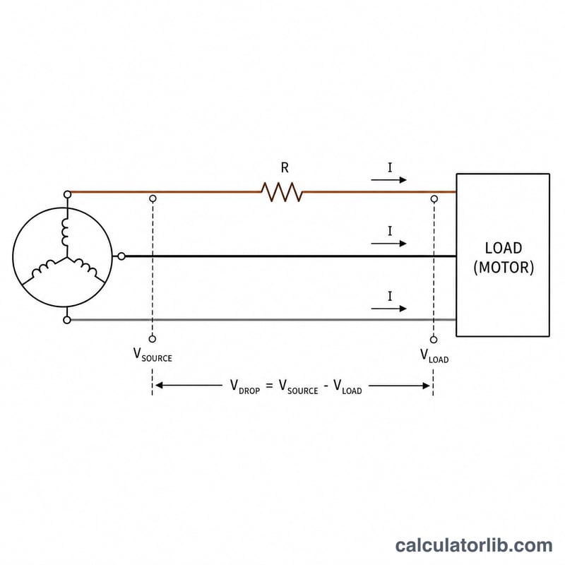
The line-to-line voltage drop is:
$$V_{drop} = \sqrt{3} \times I \times R \times \cos\phi$$where \(I\) = load current in amperes, \(R\) = one-way conductor resistance in ohms, and \(\cos\phi\) = power factor. The conductor resistance is found from:
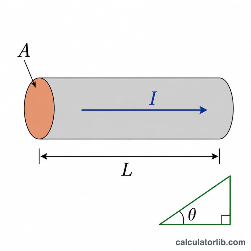
$$R = \frac{\rho \, L}{A}$$with \(\rho\) = resistivity in \(\Omega\cdot\text{mm}^2/\text{m}\) (about 0.0175 for copper, 0.028 for aluminium), \(L\) = one-way length in metres, and \(A\) = cross-sectional area in \(\text{mm}^2\). The percentage drop is \(\frac{V_{drop}}{V_{LL}} \times 100\).
How to Use It
Enter the load current, the one-way cable length, the conductor material resistivity, the cross-sectional area, the power factor, and the line-to-line system voltage. The calculator returns the volts dropped, the percentage drop, the conductor resistance, and the resulting voltage at the load.
Worked Example
A 30 A load is fed by a 50 m run of 10 mm² copper (\(\rho = 0.0175\)) at power factor 0.9 on a 400 V system. The resistance is:
$$R = \frac{0.0175 \times 50}{10} = 0.0875\,\Omega$$The voltage drop is:
$$V_{drop} = \sqrt{3} \times 30 \times 0.0875 \times 0.9 \approx 4.09\,\text{V}$$which is about \(1.02\%\) of 400 V — well within typical limits.
FAQ
Why the \(\sqrt{3}\) factor? In a balanced three-phase system the line-to-line drop relates to the per-phase drop by \(\sqrt{3}\), giving the familiar \(\sqrt{3} \, I R \cos\phi\) expression.
Should I include reactance? This simplified model uses only resistance, which is accurate for small cables. For large conductors and long runs, cable reactance \(X\sin\phi\) also contributes and increases the drop.
One-way or round-trip length? Enter the one-way length. The three-phase formula already accounts for the conductor geometry, so you do not double the distance.