What this pipe size calculator does
Sizing a pipe is a balance: a bore that is too small drives velocity and friction loss up, causing noise, erosion and wasted pump energy, while an oversized bore wastes material and can let solids settle. This tool takes the volumetric flow rate you need to move and the mean velocity you want to design for, then returns the smallest inside diameter that satisfies both, in millimetres and inches, together with the required cross-sectional area and the next standard nominal size.
How to use it
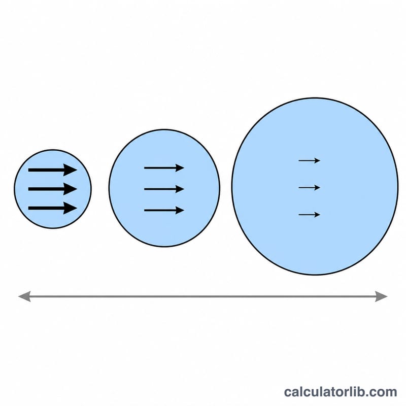
Enter the flow rate and pick its unit (L/s, L/min, m³/h, US GPM or cfs). Then enter your target velocity in m/s or ft/s. For clean water, common design practice is roughly 0.9-2.4 m/s (3-8 ft/s) on pressure lines and under 1.2 m/s on suction lines. Lower the velocity and the calculator returns a bigger pipe.
The formula explained
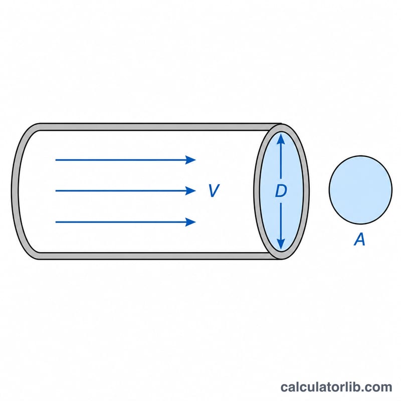
Continuity says flow equals area times velocity, \(Q = A \times v\), so the area you need is \(A = Q / v\). A circular pipe of inside diameter \(d\) has \(A = \pi d^{2}/4\), and solving for \(d\) gives:
$$d = \sqrt{\frac{4Q}{\pi v}}$$where \(Q\) = volumetric flow in m³/s, \(v\) = mean velocity in m/s and \(d\) = inside diameter in metres.
Worked example
You must carry 10 L/s of water at 2 m/s. First convert: \(Q = 0.01\) m³/s. The area needed is
$$A = \frac{0.01}{2} = 0.005\,\text{m}^2 = 50\,\text{cm}^2$$and the diameter is
$$d = \sqrt{\frac{4 \times 0.005}{\pi}} = 0.0798\,\text{m} = 79.8\,\text{mm} \approx 3.14\,\text{in}$$No stock pipe has a 3.14 in bore, so you step up to a 4 in nominal line, where the same flow travels at only about 1.23 m/s.
Flow Rate and Velocity Unit Conversions
The diameter formula is dimensionally consistent only in SI base units: flow \(Q\) in m³/s and velocity \(V\) in m/s give \(D\) in metres. The calculator applies the factor \(k\) for whichever flow unit you select, then converts the answer to millimetres and inches. The factors are exact or exactly-derived values, not approximations of convenience.
| Unit | Calculator code | Multiply by to get m³/s | Equivalent in L/s |
|---|---|---|---|
| litres per second (L/s) | lps | 0.001 (exact) | 1 |
| litres per minute (L/min) | lpm | 1.6667 × 10⁻⁵ | 0.016667 |
| cubic metres per hour (m³/h) | m3h | 2.7778 × 10⁻⁴ | 0.27778 |
| US gallons per minute (US GPM) | gpm | 6.3090 × 10⁻⁵ | 0.063090 |
| cubic feet per second (cfs) | cfs | 0.028317 | 28.317 |
Cross-conversions for one litre per second
$$1\ \text{L/s} = 60\ \text{L/min} = 3.6\ \text{m}^3/\text{h} = 15.85\ \text{US GPM} = 0.03531\ \text{cfs} = 0.001\ \text{m}^3/\text{s}$$
| Given | L/s | L/min | m³/h | US GPM | cfs |
|---|---|---|---|---|---|
| 1 L/s | 1 | 60 | 3.6 | 15.85 | 0.03531 |
| 1 L/min | 0.01667 | 1 | 0.06 | 0.2642 | 0.000589 |
| 1 m³/h | 0.2778 | 16.67 | 1 | 4.403 | 0.009810 |
| 1 US GPM | 0.06309 | 3.785 | 0.2271 | 1 | 0.002228 |
| 1 cfs | 28.317 | 1 699 | 101.9 | 448.8 | 1 |
Velocity
$$1\ \text{m/s} = 3.2808\ \text{ft/s} \qquad 1\ \text{ft/s} = 0.3048\ \text{m/s}\ \text{(exact)}$$
| m/s | ft/s | Typical association |
|---|---|---|
| 0.61 | 2.00 | Self-cleansing minimum for sanitary sewers (US Ten-State Standards) |
| 1.00 | 3.28 | Conservative pump suction |
| 1.22 | 4.00 | Copper hot-recirculation erosion limit |
| 1.50 | 4.92 | Upper end of building water distribution |
| 2.00 | 6.56 | Typical pumped water main |
| 3.00 | 9.84 | Upper end of chilled water |
| 9.00 | 29.5 | Upper end of compressed-air mains |
| 30.0 | 98.4 | Mid-range saturated steam |
Diameter and area units in the output
- \(1\ \text{in} = 25.4\ \text{mm}\) (exact), so \(D\,[\text{in}] = D\,[\text{mm}] / 25.4\)
- \(1\ \text{m} = 1\,000\ \text{mm} = 39.370\ \text{in}\)
- \(1\ \text{m}^2 = 10\,000\ \text{cm}^2 = 1\,000\,000\ \text{mm}^2 = 1\,550\ \text{in}^2\)
- \(1\ \text{in}^2 = 645.16\ \text{mm}^2\) (exact)
- Area from diameter: \(A = \pi D^2 / 4\); for \(D\) in mm the area is in mm², for \(D\) in m it is in m²
Worked unit path
A duty of 120 US GPM at 5 ft/s converts first, then substitutes:
$$Q = 120 \times 6.3090\times10^{-5} = 7.571\times10^{-3}\ \text{m}^3/\text{s} \qquad V = 5 \times 0.3048 = 1.524\ \text{m/s}$$$$D = \sqrt{\frac{4 \times 7.571\times10^{-3}}{\pi \times 1.524}} = \sqrt{6.3251\times10^{-3}} = 0.07953\ \text{m} = 79.5\ \text{mm} = 3.13\ \text{in}$$Two traps worth naming
- US gallons are not Imperial gallons. 1 Imperial GPM = 1.201 US GPM = 4.546 L/min, while 1 US GPM = 3.785 L/min. The
gpmoption in this calculator is US gallons per minute, the convention in US and Canadian practice; data taken from older UK or Commonwealth sources in Imperial GPM must be multiplied by 1.201 before entry, or the pipe will be undersized by about 10 % in diameter. - Gas flows need a stated reference condition. Volumetric units for air, steam or natural gas (Nm³/h, SCFM, ACFM) are only meaningful at a given pressure and temperature. Convert to actual volumetric flow at the operating condition in the pipe before sizing, since velocity depends on actual, not standard, volume.
FAQ
Is nominal size the same as inside diameter? No. NPS and DN labels are nominal; the true bore depends on wall schedule. Always confirm the published inside diameter for your schedule, then re-check velocity with \(v = 4Q/(\pi d^{2})\).
Does this account for pressure drop? Not directly. Velocity-based sizing is the standard first pass; follow it with a friction-loss check (Darcy-Weisbach or Hazen-Williams) over the real pipe length and fittings.
What about gases or viscous fluids? The geometry is identical, but target velocities differ widely: compressed air and steam lines run far faster, thick slurries far slower. Use the velocity limit your code or supplier recommends for that fluid.