What this calculator is
This tool applies to the United States and follows the National Electrical Code (NFPA 70), using Table 310.16 ampacities for conductors in a raceway or cable, the ambient-temperature correction factors of 310.15(B)(1) (based on a 30 °C table ambient) and the conductor-count adjustment of 310.15(C)(1). It sizes copper or aluminum conductors from 14 AWG through 500 kcmil. Outside the US, use your own national wiring rules.
How to use it
Enter the load current, the system voltage, whether the circuit is single or three phase, and the one-way run length. Choose the conductor material and the insulation temperature column your terminations allow (most 100 A and smaller equipment is limited to the 75 °C column by NEC 110.14(C)). Add the ambient temperature and how many current-carrying conductors share the raceway, then set a voltage-drop target — 3% for a branch circuit is the usual informational recommendation.
The formula
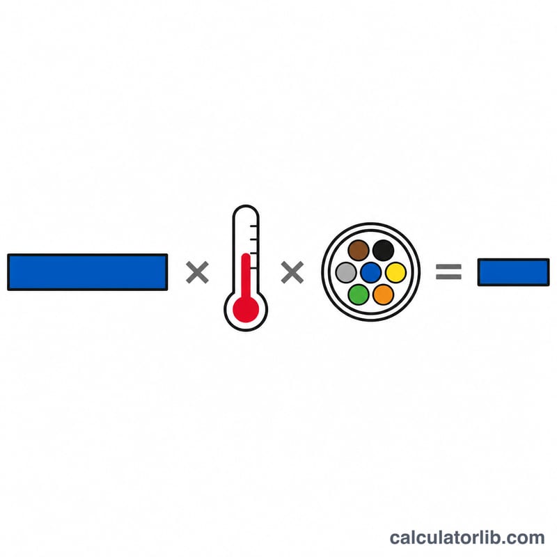
First the required table ampacity, where \(I_{load}\) = load current in amps, \(F_{cont}\) = 1.25 for a continuous load, \(C_{temp}\) = ambient correction and \(C_{fill}\) = conductor-count adjustment:
$$A_{req} = \frac{I_{load} \times F_{cont}}{C_{temp} \times C_{fill}}$$Then the smallest conductor whose table ampacity reaches \(A_{req}\) is checked for voltage drop, with \(L\) = one-way feet and \(CM\) = circular mils:
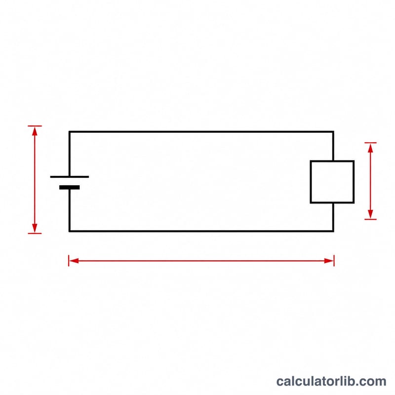
$$V_{drop} = \frac{M \times K \times I \times L}{CM}$$The calculator returns whichever size is larger — the ampacity pick or the voltage-drop pick.
Worked example
A 40 A non-continuous load at 240 V, single phase, 100 ft one way, copper, 75 °C column, 30 °C ambient, three conductors. Corrections are 1.00, so \(A_{req} = 40\) A and 8 AWG copper (50 A) is the smallest that qualifies. Checking drop with \(CM = 16510\):
$$V_{drop} = \frac{2 \times 12.9 \times 40 \times 100}{16510} = 6.25\,\text{V} = 2.6\%$$That is under 3%, so 8 AWG copper is the answer.
NEC Ampacity and Correction Factor Tables
The tables below are from the United States National Electrical Code (NFPA 70). They apply only where the NEC has been adopted as law (US states and territories, and jurisdictions that reference it). Other countries use different rules — IEC 60364 / BS 7671 in the UK, CSA C22.1 in Canada, AS/NZS 3000 in Australia — and their current-carrying-capacity tables are not interchangeable with these. Values reflect the widely used NEC 2017/2020/2023 editions; always verify against the code edition actually adopted by your local authority having jurisdiction (AHJ). This page is reference material, not a substitute for the printed code or a licensed electrician.
Table 310.16 — Allowable Ampacities of Insulated Conductors
Not more than three current-carrying conductors in a raceway, cable, or directly buried; ambient temperature 30 °C (86 °F).
| Size (AWG/kcmil) | Copper (A) | Aluminum / Cu-clad Al (A) | ||||
|---|---|---|---|---|---|---|
| 60 °C | 75 °C | 90 °C | 60 °C | 75 °C | 90 °C | |
| 14 | 15 | 20 | 25 | — | — | — |
| 12 | 20 | 25 | 30 | 15 | 20 | 25 |
| 10 | 30 | 35 | 40 | 25 | 30 | 35 |
| 8 | 40 | 50 | 55 | 30 | 40 | 45 |
| 6 | 55 | 65 | 75 | 40 | 50 | 55 |
| 4 | 70 | 85 | 95 | 55 | 65 | 75 |
| 3 | 85 | 100 | 115 | 65 | 75 | 85 |
| 2 | 95 | 115 | 130 | 75 | 90 | 100 |
| 1 | 110 | 130 | 145 | 85 | 100 | 115 |
| 1/0 | 125 | 150 | 170 | 100 | 120 | 135 |
| 2/0 | 145 | 175 | 195 | 115 | 135 | 150 |
| 3/0 | 165 | 200 | 225 | 130 | 155 | 175 |
| 4/0 | 195 | 230 | 260 | 150 | 180 | 205 |
| 250 | 215 | 255 | 290 | 170 | 205 | 230 |
| 300 | 240 | 285 | 320 | 195 | 230 | 260 |
| 350 | 260 | 310 | 350 | 210 | 250 | 280 |
| 400 | 280 | 335 | 380 | 225 | 270 | 305 |
| 500 | 320 | 380 | 430 | 260 | 310 | 350 |
Aluminum is not listed at 14 AWG in Table 310.16. Note also that the 90 °C column is generally used only for applying correction and adjustment factors — the final ampacity is still limited by the terminal rating under 110.14(C), and small conductors are further limited by 240.4(D).
Table 310.15(B)(1) — Ambient Temperature Correction Factors
Multipliers \(F_{temp}\) applied to the Table 310.16 value when the ambient temperature differs from the 30 °C table basis.
| Ambient (°C) | Ambient (°F) | 60 °C column | 75 °C column | 90 °C column |
|---|---|---|---|---|
| 10 or less | 50 or less | 1.29 | 1.20 | 1.15 |
| 11–15 | 51–59 | 1.22 | 1.15 | 1.12 |
| 16–20 | 60–68 | 1.15 | 1.11 | 1.08 |
| 21–25 | 69–77 | 1.08 | 1.05 | 1.04 |
| 26–30 | 78–86 | 1.00 | 1.00 | 1.00 |
| 31–35 | 87–95 | 0.91 | 0.94 | 0.96 |
| 36–40 | 96–104 | 0.82 | 0.88 | 0.91 |
| 41–45 | 105–113 | 0.71 | 0.82 | 0.87 |
| 46–50 | 114–122 | 0.58 | 0.75 | 0.82 |
| 51–55 | 123–131 | 0.41 | 0.67 | 0.76 |
| 56–60 | 132–140 | — | 0.58 | 0.71 |
| 61–70 | 141–158 | — | 0.33–0.47 | 0.58–0.65 |
| 71–80 | 159–176 | — | — | 0.41–0.50 |
Table 310.15(C)(1) — Adjustment Factors for More Than Three Current-Carrying Conductors
Multipliers \(F_{fill}\) applied when more than three current-carrying conductors share a raceway or cable for more than 600 mm (24 in).
| Number of current-carrying conductors | Percent of table value | Factor |
|---|---|---|
| 1–3 | 100% | 1.00 |
| 4–6 | 80% | 0.80 |
| 7–9 | 70% | 0.70 |
| 10–20 | 50% | 0.50 |
| 21–30 | 45% | 0.45 |
| 31–40 | 40% | 0.40 |
| 41 and above | 35% | 0.35 |
Both factors apply together when both conditions exist: \(A_{corrected}=A_{table}\times F_{temp}\times F_{fill}\).
Circular-Mil Areas by Conductor Size (NEC Chapter 9, Table 8)
These areas are the \(CM\) values compared against the voltage-drop requirement.
| Size | Area (circular mils) | Size | Area (circular mils) |
|---|---|---|---|
| 14 AWG | 4,107 | 1/0 | 105,600 |
| 12 AWG | 6,530 | 2/0 | 133,100 |
| 10 AWG | 10,380 | 3/0 | 167,800 |
| 8 AWG | 16,510 | 4/0 | 211,600 |
| 6 AWG | 26,240 | 250 kcmil | 250,000 |
| 4 AWG | 41,740 | 300 kcmil | 300,000 |
| 3 AWG | 52,620 | 350 kcmil | 350,000 |
| 2 AWG | 66,360 | 400 kcmil | 400,000 |
| 1 AWG | 83,690 | 500 kcmil | 500,000 |
One kcmil equals 1,000 circular mils; a circular mil is the area of a circle 0.001 in in diameter, so \(CM = d_{mils}^{2}\) for a round solid conductor.
Key Terms and Variables
Terminology below follows NEC Article 100 definitions and US wiring practice.
- Ampacity
- The maximum current, in amperes, a conductor can carry continuously under the conditions of use without exceeding its temperature rating (NEC Article 100). It is a property of the conductor plus its installation — insulation type, ambient temperature, number of conductors bundled together — not of the metal alone.
- AWG and kcmil
- American Wire Gauge is the US sizing system; the number gets smaller as the wire gets larger (14 AWG is thin, 4/0 is thick). Above 4/0 AWG, sizes are stated in thousands of circular mils: 250 kcmil, 500 kcmil, and so on. AWG sizes do not correspond to the mm² sizes used almost everywhere else in the world.
- Circular mil (cmil)
- The area of a circle 0.001 inch in diameter. For a round solid conductor the area in circular mils is simply the diameter in mils squared, \(CM=d^{2}\), which is why the voltage-drop formula solves directly for circular mils rather than square inches.
- Insulation temperature rating (60 / 75 / 90 °C columns)
- The maximum continuous operating temperature the conductor insulation can withstand. Common US types: TW at 60 °C; THW, THWN, RHW and USE at 75 °C; THHN, THWN-2, XHHW-2 and RHH at 90 °C. A higher column means a higher table ampacity, but only if the terminations permit it.
- Termination temperature limitation (110.14(C))
- Even with 90 °C wire, the circuit ampacity is limited by the temperature rating of the equipment terminals. In the US this normally means the 60 °C column for circuits rated 100 A or less (or marked for 14–1 AWG conductors) and the 75 °C column above that, unless the equipment is listed and marked for higher. The 90 °C column is generally used only as the starting point for applying ambient and bundling factors.
- Current-carrying conductor
- A conductor that actually carries load current and therefore generates heat inside the raceway. Equipment grounding conductors are excluded because they carry current only during a fault. A neutral is excluded when it carries only the unbalanced current of a multiwire circuit; it is counted on a 3-wire circuit derived from a 4-wire wye where it carries full current, and where the load is substantially nonlinear (harmonic-rich) so the neutral carries appreciable current. See NEC 310.15(E).
- Continuous load
- A load whose maximum current is expected to persist for 3 hours or more (NEC Article 100) — lighting, EV charging, HVAC, sign circuits. Conductors and the overcurrent device must be sized at 125% of that load.
- Ambient temperature
- The temperature of the air (or earth) surrounding the raceway or cable, not the conductor temperature. Attics, rooftops, boiler rooms and outdoor conduit in hot climates can run far above the 30 °C table basis, which shrinks the usable ampacity.
- Raceway / conduit fill
- Two separate concerns. Heating fill is the count of current-carrying conductors, which triggers the 310.15(C)(1) adjustment factors. Physical fill is the cross-sectional area limit in NEC Chapter 9, Table 1 — 53% for one conductor, 31% for two, 40% for three or more — which determines whether the wires physically fit and can be pulled.
- One-way run length
- The distance from the source (panel or supply) to the load along the cable route, measured once. The formula's multiplier (2 for single-phase or DC) already accounts for the return conductor, so do not double the length yourself.
- Voltage drop and percent voltage drop
- The voltage lost in the conductors themselves, \(V_{drop}=I\times R_{loop}\), expressed as a fraction of the nominal supply voltage: \(\%VD=\frac{V_{drop}}{V_{nominal}}\times100\). Excess drop causes dim lighting, slow motor starting, overheating motors and wasted energy. The commonly cited US targets — 3% on a branch circuit and 5% total — come from NEC Informational Notes and are recommendations rather than code requirements.
- Equipment grounding conductor vs. circuit conductor
- Circuit conductors (ungrounded/"hot" and grounded/neutral) carry normal operating current and are what this calculator sizes. The equipment grounding conductor bonds metal enclosures and carries current only under fault conditions; it is sized separately from NEC Table 250.122 based on the overcurrent device rating, and it is not counted when applying bundling adjustment factors.
General information only. Conductor sizing, overcurrent protection and installation methods are safety-critical and legally regulated — have the design reviewed against the code edition adopted in your jurisdiction and, where required, performed or inspected by a licensed electrician.
FAQ
Why does aluminum need a bigger size? Aluminum is roughly 61% as conductive as copper, so both its ampacity and its voltage drop are worse for the same circular mils — typically two AWG sizes larger.
Can I use the 90 °C column? Only for derating. The final ampacity must not exceed the rating of the terminations, which is usually 60 °C or 75 °C.
Does this pick the breaker? No. Overcurrent protection follows NEC 240.4, including the 15/20/30 A small-conductor limits for 14/12/10 AWG copper.