What is duct static pressure loss?
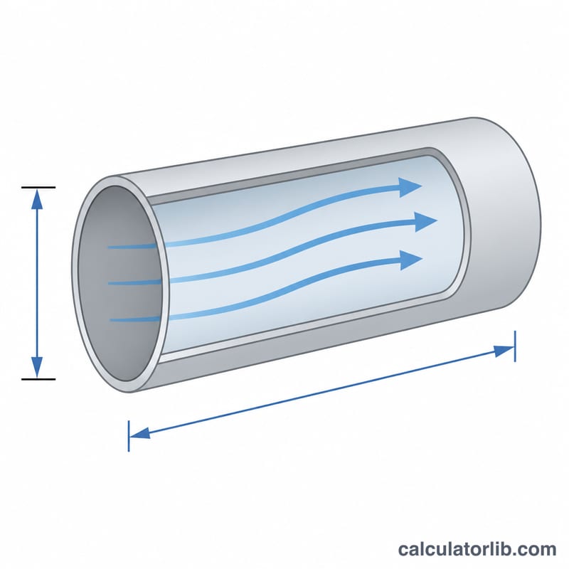
Static pressure loss is the energy an HVAC fan must overcome to push air through ductwork. As air moves along a duct, friction between the airstream and the sheet-metal wall creates a steady pressure drop measured in inches of water column (in.wc). Knowing this loss helps you size fans, balance airflow, and avoid noisy, undersized runs.
How to use this calculator
Enter the airflow in cubic feet per minute (CFM), the round duct diameter in inches, and the straight run length in feet. The tool returns the friction rate per 100 feet and the total static pressure loss for the run. For rectangular ducts, first convert to an equivalent round diameter.
The formula explained
This calculator uses the widely referenced ASHRAE friction-rate equation for round galvanized ducts, where \(Q\) = airflow in CFM, \(d\) = duct diameter in inches, and \(L\) = run length in feet:
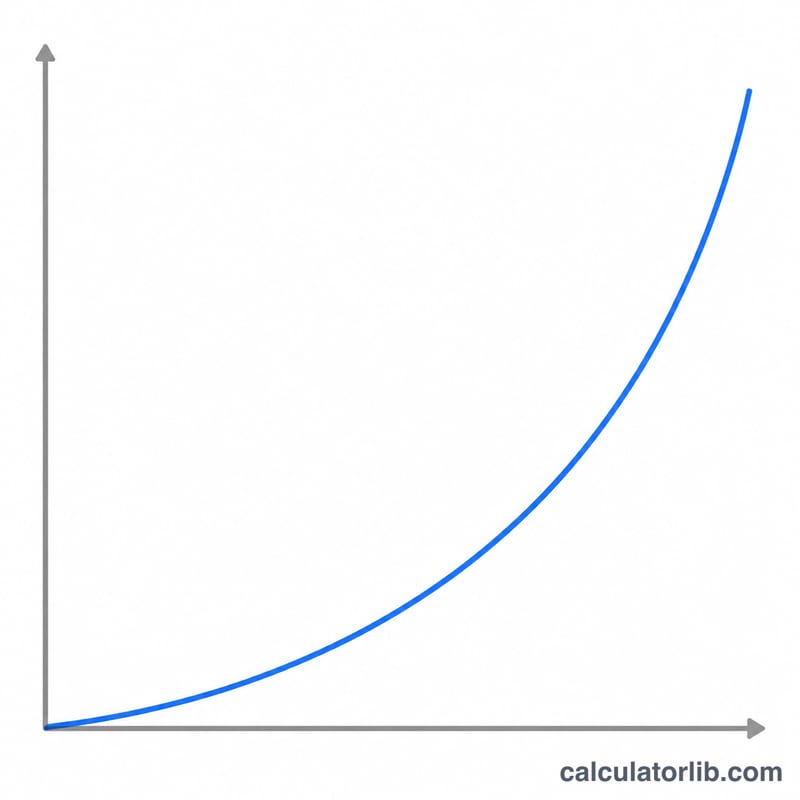
$$\Delta P = 0.109136 \times \dfrac{Q^{1.9}}{d^{5.02}} \times \dfrac{L}{100}$$The first term gives the friction rate in in.wc per 100 feet, and the length ratio scales it to your actual run.
Worked example
Suppose you move \(1000\) CFM through a \(12\) inch duct over a \(100\) foot run:
$$F_r = 0.109136 \times \dfrac{1000^{1.9}}{12^{5.02}} \approx 0.209\ \text{in.wc/100 ft}$$$$\Delta P = 0.209 \times \dfrac{100}{100} \approx 0.209\ \text{in.wc}$$This is close to the classic target friction rate of about 0.1 to 0.2 in.wc per 100 feet used in residential design.
Typical Friction Rate and Velocity Ranges
Duct designers usually start from a target friction rate (in. wc per 100 ft of duct) and then size ducts for that rate. The ranges below are commonly cited rules of thumb based on ASHRAE Handbook—Fundamentals and SMACNA duct design guidance (US inch-pound units). They are guidelines, not code requirements. Your local code, equipment manufacturer data and project specifications take priority.
Design friction rate
| Application | Common design friction rate (in. wc / 100 ft) |
|---|---|
| Residential and light commercial low-pressure systems | about 0.08–0.10 |
| Higher-pressure or space-constrained designs | up to roughly 0.2 (fan power and noise increase) |
Typical duct velocities (approximate)
| Duct section | Residential (fpm) | Commercial low-velocity (fpm) |
|---|---|---|
| Supply main | 700–900 | 1,200–2,000 |
| Supply branch | about 600 | 800–1,200 |
| Return main / branch | 600–700 | 800–1,500 |
Noise is usually the limiting factor for velocity. Higher velocities raise air noise at fittings, grilles and diffusers, so ducts near occupied spaces use the lower end of each range. Mains in mechanical rooms or above ceilings can tolerate more. Velocity follows from \(V = Q / A\), with airflow \(Q\) in CFM and area \(A\) in ft².
Rectangular-to-Round Equivalent Diameters and Fitting Equivalent Lengths
The friction-rate formula applies to round duct. For rectangular duct, convert to the round diameter that gives equal friction at the same airflow using the Huebscher equation, where \(a\) and \(b\) are the side dimensions in inches:
$$D_e = \frac{1.30\,(ab)^{0.625} }{(a+b)^{0.25} }$$
| Rectangular size (in) | Calculation | Equivalent round diameter (in) |
|---|---|---|
| 8 × 6 | 1.30 × 480.625 / 140.25 = 1.30 × 11.24 / 1.934 | ≈ 7.6 |
| 10 × 8 | 1.30 × 800.625 / 180.25 = 1.30 × 15.47 / 2.060 | ≈ 9.8 |
| 12 × 8 | 1.30 × 960.625 / 200.25 = 1.30 × 17.33 / 2.115 | ≈ 10.7 |
| 14 × 10 | 1.30 × 1400.625 / 240.25 = 1.30 × 21.94 / 2.213 | ≈ 12.9 |
The equivalent diameter gives the same friction rate at the same airflow, but the rectangular duct has a different cross-sectional area and velocity. Aspect ratios above about 4:1 are generally avoided.
Approximate fitting equivalent lengths (feet of straight duct)
These are rough, illustrative values for round duct, based on typical loss coefficients and an assumed friction factor. They are approximate and vary widely with fitting geometry. For design, use the loss coefficients in the ASHRAE Duct Fitting Database and SMACNA fitting data.
| Fitting | 8 in duct (ft) | 10 in duct (ft) | 12 in duct (ft) |
|---|---|---|---|
| 90° smooth-radius elbow | ≈ 7 | ≈ 8 | ≈ 10 |
| 45° elbow | ≈ 4 | ≈ 4 | ≈ 5 |
| Branch tee (takeoff) | ≈ 17 | ≈ 21 | ≈ 25 |
| Gradual transition | ≈ 3 | ≈ 4 | ≈ 4 |
To include fittings, add their equivalent lengths to the straight length before entering the total length. Sharp mitered elbows without turning vanes can be several times worse than the smooth-radius values shown.
FAQ
Does this include fittings? No. It covers straight-duct friction only. Add equivalent lengths or fitting loss coefficients for elbows and transitions.
What is a good friction rate? Many designers aim for roughly 0.08 to 0.10 in.wc per 100 feet to keep velocity and noise reasonable.
Can I use it for flex duct? Flexible duct has higher friction; multiply the result by a correction factor of about 1.5 to 2.