What Is a Fiber Optic Loss Budget?
A fiber optic loss budget (also called an optical power budget or link budget) totals up every source of signal attenuation along a fiber link and compares it against the power your transmitter can deliver. If the total loss exceeds the available power budget, the receiver will not see a strong enough signal and the link will fail or suffer errors. This calculator works for any fiber type or jurisdiction — the physics of dB loss is universal.
How to Use This Calculator
Enter the cable length in kilometres and the fiber's attenuation coefficient (typical single-mode is about 0.35 dB/km at 1310 nm, or 0.22 dB/km at 1550 nm; multimode is higher). Add the number of connectors and the loss per connector (often 0.3–0.75 dB each), then the number of fusion splices and loss per splice (around 0.1 dB each). Optionally enter your transmitter output power and receiver sensitivity in dBm to see the available budget and remaining link margin.
The Formula Explained
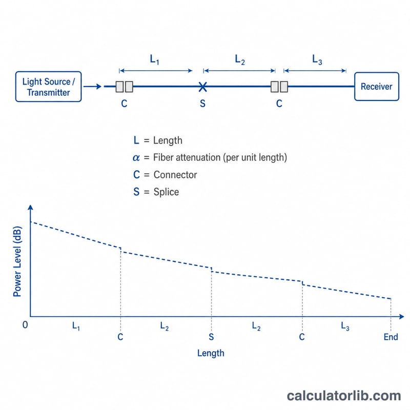
Total loss is simply: Loss = (length × fiber dB/km) + (connectors × dB) + (splices × dB).
$$\text{Margin} = (\text{Tx Power} - \text{Rx Sensitivity}) - L_{\text{total}}$$$$\text{where}\quad \left\{ \begin{aligned} L_{\text{total}} &= \text{Length} \cdot \text{Fiber Att.} \\ &\quad + \text{Connectors} \cdot \text{Loss/Conn.} \\ &\quad + \text{Splices} \cdot \text{Loss/Splice} \end{aligned} \right.$$The available power budget equals transmitter power minus receiver sensitivity. The link margin is the available budget minus the total loss — engineers usually want a positive margin of at least 3 dB to allow for ageing, repairs, and temperature drift.
Worked Example
A 10 km single-mode run at 0.35 dB/km gives 3.5 dB of fiber loss. With 4 connectors at 0.5 dB you add 2.0 dB, and 2 splices at 0.1 dB add 0.2 dB. Total loss =
$$3.5 + 2.0 + 0.2 = \mathbf{5.7\ \text{dB}}$$If the transmitter outputs 0 dBm and the receiver sensitivity is −23 dBm, the available budget is 23 dB, leaving a healthy margin of \(23 - 5.7 = 17.3\ \text{dB}\).
FAQ
What is a good link margin? Aim for at least 3 dB above zero to cover future splices and component degradation.
Why is my margin negative? The total loss exceeds what your optics can deliver — use lower-loss fiber, fewer connectors, a stronger transmitter, or a more sensitive receiver.
Do connectors really matter that much? Yes. On short links connector and splice losses can dominate the budget, so count every mated pair.