What is the Pipe Sizing Calculator?
This calculator determines the inside pipe diameter you need to carry a given volumetric flow rate at a chosen design velocity. Picking the right diameter keeps velocity in a sensible band: too small and friction losses and pressure drop spike, too large and the system costs more than necessary. It is built on the continuity equation, the same relationship engineers use to size water, HVAC, and process piping.
The formula explained
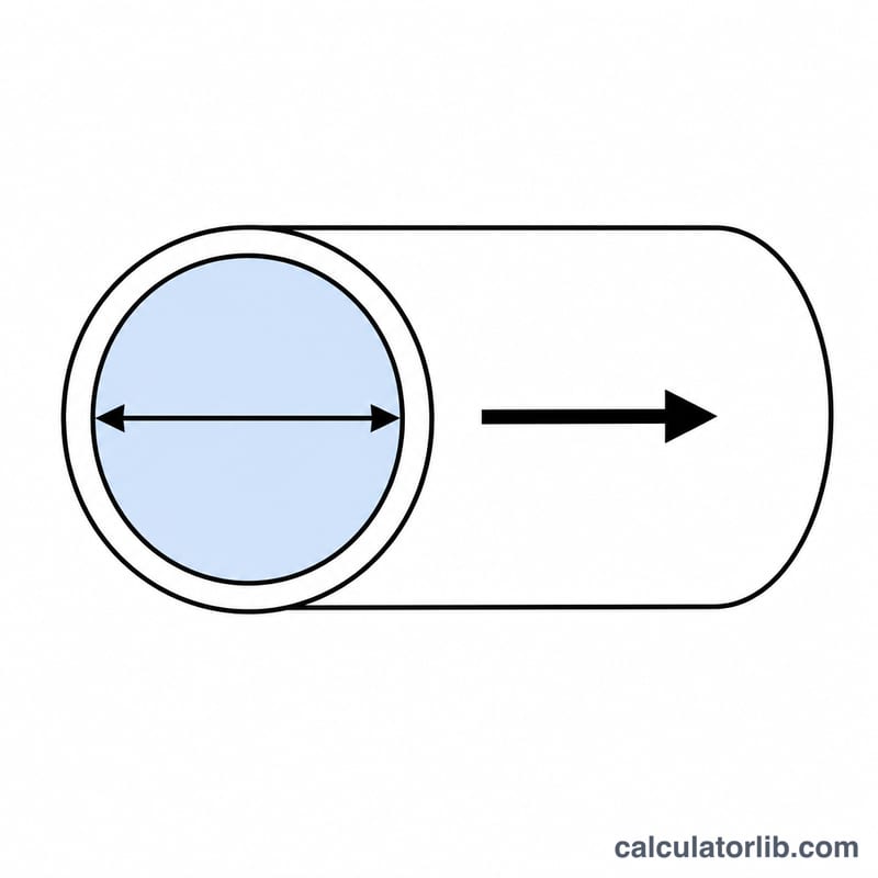
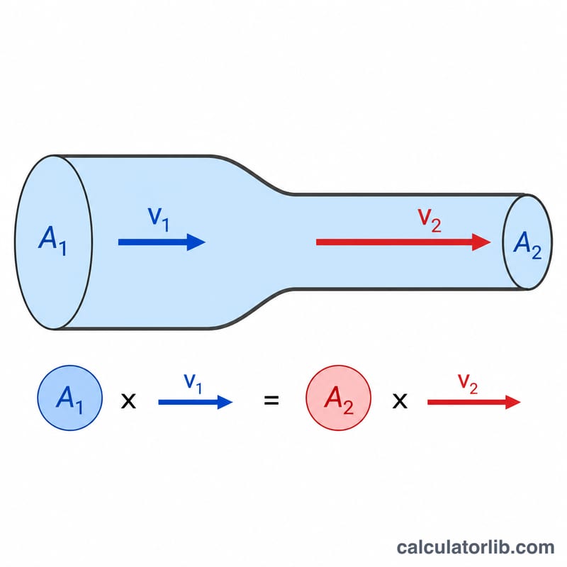
Flow rate \(Q\), velocity \(v\), and flow area \(A\) are linked by continuity, \(Q = A \times v\). Because a round pipe has area \(A = \tfrac{\pi d^2}{4}\), solving for the diameter \(d\) gives:
$$d = \sqrt{\dfrac{4Q}{\pi v}}$$Here \(Q\) = volumetric flow rate in cubic metres per second, \(v\) = design velocity in metres per second, and \(d\) = inside diameter in metres. This tool accepts flow in m³/h and converts it with \(Q_{\text{m}^3/\text{s}} = Q_{\text{m}^3/\text{h}}/3600\), then reports the diameter in millimetres.
How to use it
Enter the flow rate the pipe must carry in m³/h and the target velocity in m/s. Typical design velocities are roughly 1–3 m/s for liquid lines. The calculator returns the minimum required inside diameter and the flow area; in practice you round up to the next standard pipe size.
Worked example
Suppose \(Q = 36\) m³/h at \(v = 2\) m/s. Convert the flow: \(Q = 36/3600 = 0.01\) m³/s. The required area is
$$A = \dfrac{Q}{v} = \dfrac{0.01}{2} = 0.005\ \text{m}^2$$and the diameter is
$$d = \sqrt{\dfrac{4 \times 0.005}{\pi}} = 0.0798\ \text{m} = 79.8\ \text{mm}$$So you would select the next standard pipe at or above about 80 mm.
Standard Pipe Sizes (DN / NPS)
Commercial pipe is not made in every diameter — it comes in standardized nominal sizes. Two naming systems are common: the metric DN (Diamètre Nominal) and the inch-based NPS (Nominal Pipe Size). Both are labels, not the actual bore: the outside diameter (OD) is fixed for a given size, while the inside diameter (ID) changes with wall thickness (schedule). The approximate IDs below are for Schedule 40 steel pipe per ASME B36.10M; a heavier schedule (e.g. Sch 80) has a thicker wall and therefore a smaller ID for the same nominal size. Always use the ID for your specific schedule when sizing to a computed diameter.
| DN (metric) | NPS (inch) | Outside diameter (mm) | Approx. inside diameter, Sch 40 (mm) |
|---|---|---|---|
| DN15 | ½" | 21.3 | 15.8 |
| DN20 | ¾" | 26.7 | 20.9 |
| DN25 | 1" | 33.4 | 26.6 |
| DN32 | 1¼" | 42.2 | 35.1 |
| DN40 | 1½" | 48.3 | 40.9 |
| DN50 | 2" | 60.3 | 52.5 |
| DN65 | 2½" | 73.0 | 62.7 |
| DN80 | 3" | 88.9 | 77.9 |
| DN100 | 4" | 114.3 | 102.3 |
| DN150 | 6" | 168.3 | 154.1 |
| DN200 | 8" | 219.1 | 202.7 |
Once the calculator gives you a required inside diameter, round up to the next standard size whose ID is at least as large — a slightly larger pipe simply lowers the velocity, whereas an undersized one raises velocity, friction and noise. Note that plastic (PVC/PE) and copper tube use their own dimension standards, so their IDs differ from the steel values above even at the same nominal label.
Typical Design Velocities by Service
The design velocity you enter is a trade-off. A higher velocity lets you use a smaller (cheaper) pipe but increases friction loss, pumping energy, noise and erosion. A lower velocity reduces those effects but requires a larger, more expensive pipe and can allow solids to settle. The ranges below reflect widely used engineering practice (e.g. ASHRAE guidance for HVAC water systems, and general piping handbooks such as Crane Technical Paper 410); they are typical starting points, not hard limits — your local codes, fluid, and project specification take precedence.
| Service | Typical design velocity (m/s) | Notes |
|---|---|---|
| Water — pump suction | 0.6 – 1.5 | Kept low to protect against cavitation (NPSH). |
| Water — pump discharge / general liquid | 1 – 3 | Common default for process and service water. |
| Long liquid pipelines | 1 – 2 | Lower end favoured to limit friction over distance. |
| HVAC chilled / hot water | 1 – 3 | Upper end can cause noise in occupied spaces. |
| Saturated / low-pressure steam | 15 – 40 | Gases and steam run far faster than liquids. |
| Compressed air / gas lines | 10 – 30 | Higher velocities increase pressure drop sharply. |
As a rule of thumb, size for the lower end of the range where energy cost, noise or erosion matters (e.g. continuously running or occupied-space systems), and toward the higher end where minimizing pipe cost is the priority and the fluid is clean and non-abrasive. For gases and steam, velocity is usually limited by acceptable pressure drop and noise rather than by a single fixed value, so treat those figures as broad guidance and confirm against the applicable standard for your system.
FAQ
What velocity should I choose? For water and similar liquids, 1–3 m/s is common; higher velocities raise friction losses and noise, lower ones increase cost.
Does this include pressure drop? No, it sizes the pipe from flow and velocity; friction pressure drop is a separate calculation once the diameter is fixed.
Is the result an exact pipe size? It is the minimum theoretical inside diameter. Always round up to the nearest commercially available pipe.