What is the steel bar spacing calculator?
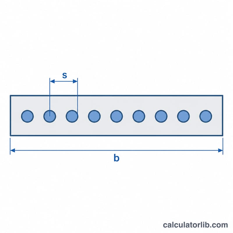
This calculator finds how far apart reinforcing bars should be placed so that a slab, footing or beam strip receives at least the steel area your design calls for. Enter the required area, the strip width, and the bar diameter, and you get the theoretical spacing, a practical spacing rounded down to a buildable increment, and the area actually provided. Design codes differ between countries, so always check minimum and maximum spacing and cover limits in your own code.
How to use it
Enter the required steel area in mm² for the strip (for a slab this is normally per 1000 mm width). Set the strip width, choose a bar diameter, and set the rounding step, for example 25 mm or 10 mm. The result shows spacing centre to centre, the number of bars in the strip and the percentage by which the supplied steel exceeds the requirement.
The formula explained
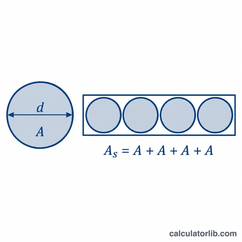
The area of one bar is \(A_b = \pi d^2 / 4\), where \(d\) is the bar diameter in mm. To supply \(A_{s,req}\) over a strip of width \(b\), the number of bars is \(A_{s,req}/A_b\), so the spacing is:
$$s = \frac{ \pi d^2 \times b}{4 \, A_{s,req}}$$The practical spacing rounds \(s\) down to the nearest multiple of the chosen step, so the steel provided is never less than required.
Worked example
A slab needs \(A_{s,req} = 1000\) mm² per metre using 12 mm bars.
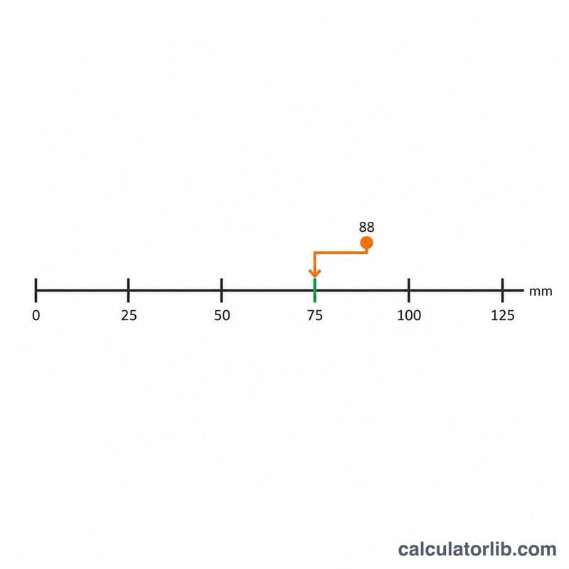
$$A_b = \frac{\pi \times 12^2}{4} = 113.1\,\text{mm}^2$$$$s = \frac{113.1 \times 1000}{1000} = 113.1\,\text{mm}$$Rounded down to a 25 mm step this gives 100 mm, so the provided area is:
$$A_{s,prov} = \frac{113.1 \times 1000}{100} = 1131\,\text{mm}^2$$That is about 13% more than required.
Steel Area per Metre Width by Bar Diameter and Spacing
The steel area provided per 1000 mm strip is \(A_s = \frac{\pi d^2}{4}\cdot\frac{1000}{s}\), with bar diameter \(d\) and spacing \(s\) in mm. Values are in mm² per metre of width, rounded to 0.1 mm².
| Bar dia (mm) | Single bar area (mm²) | 75 mm | 100 mm | 125 mm | 150 mm | 200 mm | 250 mm | 300 mm |
|---|---|---|---|---|---|---|---|---|
| 8 | 50.3 | 670.2 | 502.7 | 402.1 | 335.1 | 251.3 | 201.1 | 167.6 |
| 10 | 78.5 | 1047.2 | 785.4 | 628.3 | 523.6 | 392.7 | 314.2 | 261.8 |
| 12 | 113.1 | 1508.0 | 1131.0 | 904.8 | 754.0 | 565.5 | 452.4 | 377.0 |
| 16 | 201.1 | 2680.8 | 2010.6 | 1608.5 | 1340.4 | 1005.3 | 804.2 | 670.2 |
| 20 | 314.2 | 4188.8 | 3141.6 | 2513.3 | 2094.4 | 1570.8 | 1256.6 | 1047.2 |
| 25 | 490.9 | 6545.0 | 4908.7 | 3927.0 | 3272.5 | 2454.4 | 1963.5 | 1636.2 |
To use the table, find the row for your bar diameter and look for a spacing whose area is at least your required \(A_{s,req}\). For strips of a different width, scale the values in proportion to the width.
Typical Bar Spacing Ranges
In everyday slab and beam-slab design, bar spacing is usually between about 75 mm and 300 mm. Closer than about 75 mm becomes hard to place and compact concrete around. Wider than 300 mm is mainly limited by the maximum spacing rules below.
Commonly cited maximum spacing
- Eurocode 2 (EN 1992-1-1, cl. 9.3.1.1): main reinforcement in slabs at most the lesser of 3h or 400 mm, where h is the slab thickness. In areas of concentrated loads or maximum moments, at most the lesser of 2h or 250 mm.
- ACI 318 (United States): for two-way slabs, spacing at critical sections is at most the lesser of 2h or 450 mm. For one-way slabs, the limit is the lesser of 3h or 450 mm. ACI also sets separate limits based on shrinkage and temperature steel and on crack control.
Minimum clear spacing between parallel bars
- ACI 318: not less than the greatest of 25 mm, the bar diameter, and 4/3 of the maximum aggregate size.
- Other codes, such as Eurocode 2, use similar rules based on bar diameter, aggregate size and a minimum absolute value.
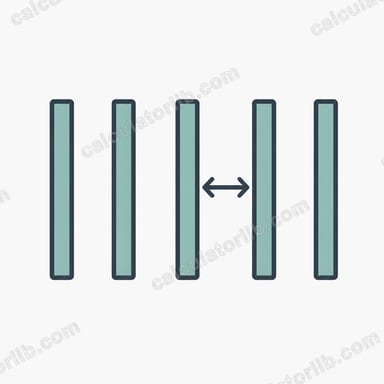
Note that clear spacing is the gap between bar surfaces, while the calculator gives centre-to-centre spacing. Clear spacing equals centre-to-centre spacing minus the bar diameter. These values are general guidance; the code and edition that apply to your project govern, along with any national annex or local amendments.
Interpreting Your Result
Theoretical spacing \(s_{th} = \frac{A_b \cdot b}{A_{s,req}}\) is the exact centre-to-centre spacing that gives precisely the required steel area. Rounded spacing rounds this value down to a practical step (for example 25 mm), so the steel provided is never less than required.
Example: \(A_{s,req} = 600\) mm²/m, width 1000 mm, 12 mm bars, rounding to 25 mm. \(A_b = \frac{\pi \cdot 12^2}{4} = 113.1\) mm², so \(s_{th} = \frac{113.1 \cdot 1000}{600} = 188.5\) mm. Rounding down to a multiple of 25 gives 175 mm. The steel provided is \(\frac{113.1 \cdot 1000}{175} = 646.3\) mm²/m, which is about 7.7% over the requirement.
Reading the over-provision
- A small excess (roughly 0–10%) is normal and comes from rounding to a buildable spacing.
- A large excess suggests the bar size or step is a poor fit. Try a smaller bar diameter or a finer rounding step.
When spacing falls outside practical limits
- Below the minimum clear spacing: bars are too tightly packed. Use a smaller bar diameter, or consider two layers.
- Above the maximum spacing: use a smaller bar diameter to bring the spacing down to the code limit.
This tool is a calculation aid only. It does not check bending, shear, cracking, deflection, cover, anchorage or detailing, and it is not a substitute for the design of a qualified structural engineer working to the governing code.
FAQ
Why round the spacing down? Rounding up would reduce the steel below the requirement. Rounding down keeps the provided area at or above the design value.
Can I use it for beams? Yes. Set the strip width to the available width between links and read the number of bars; for a beam you usually think in whole bars rather than spacing.
Does it check code limits? No. Maximum spacing, minimum spacing for concrete placement and crack control must be checked against your design code.