
What Are the Pump Affinity Laws?
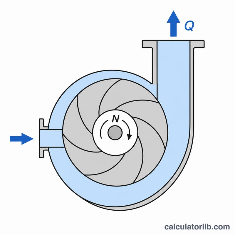
The affinity laws are a set of relationships used to predict how a centrifugal pump's performance changes when its rotational speed (or impeller diameter) is altered. They are essential for engineers sizing pumps, applying variable frequency drives (VFDs), and estimating energy savings. This calculator handles the speed-change form of the laws, computing the new flow rate, head, and shaft power for a new RPM.
How to Use This Calculator
Enter your pump's known operating point: the initial flow rate (Q₁), head (H₁), and power (P₁) at the original speed (N₁). Then enter the new speed (N₂) you plan to run at. The calculator instantly returns the predicted new flow, head, and power. The units are interchangeable — whatever units you use for Q₁, H₁, and P₁ are carried through to the results.
The Formula Explained
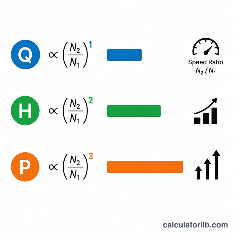
The three affinity laws are:
Flow: \(Q_2 = Q_1 \times \frac{N_2}{N_1}\) — flow is directly proportional to speed.
Head: \(H_2 = H_1\left(\frac{N_2}{N_1}\right)^2\) — head scales with the square of speed.
Power: \(P_2 = P_1\left(\frac{N_2}{N_1}\right)^3\) — power scales with the cube of speed.
The cubic relationship for power is why even modest speed reductions yield large energy savings on pumping systems.
Worked Example
A pump delivers 100 GPM at 50 ft of head, drawing 10 hp at 1750 RPM. Slowing it to 1450 RPM gives a ratio of \(1450/1750 = 0.8286\). New flow $$Q_2 = 100 \times 0.8286 = 82.9 \text{ GPM};$$ new head $$H_2 = 50 \times 0.8286^2 = 34.3 \text{ ft};$$ new power $$P_2 = 10 \times 0.8286^3 = 5.69 \text{ hp}$$ — a 43% power reduction for a 17% speed drop.
Key Terms & Variables
- Q — Flow Rate
- The volume of liquid the pump moves per unit time, commonly expressed in gallons per minute (GPM), liters per minute (LPM), or cubic meters per hour. Under the affinity laws, flow varies in direct proportion to speed: \(Q_2/Q_1 = N_2/N_1\).
- H — Head
- The height of liquid column the pump can produce, usually in feet or meters. It represents the energy added per unit weight of fluid and is independent of fluid density. Head varies with the square of the speed ratio: \(H_2/H_1 = (N_2/N_1)^2\).
- P — Shaft (Brake) Power
- The mechanical power delivered to the pump shaft by the motor, typically in horsepower (hp) or kilowatts (kW). Because power is roughly the product of flow and head, it varies with the cube of the speed ratio: \(P_2/P_1 = (N_2/N_1)^3\).
- N — Rotational Speed (RPM)
- The angular speed of the pump impeller in revolutions per minute. Changing N is the input that drives all three affinity-law predictions. \(N_1\) is the original speed and \(N_2\) is the new operating speed.
- VFD — Variable Frequency Drive
- An electronic controller that varies the frequency (and voltage) supplied to an AC motor, thereby adjusting the pump's RPM. VFDs let operators exploit the cubic power law to match output to demand and reduce energy consumption.
- Impeller
- The rotating component with curved vanes that imparts kinetic energy to the fluid. The affinity laws presented here assume the impeller diameter is held constant and only speed changes; a separate set of affinity relations applies when diameter is trimmed.
- System Curve
- A plot of the head a piping system requires versus flow rate. The pump's actual operating point is where its performance curve intersects the system curve; the affinity laws shift the pump curve, but the realized point still depends on the system curve.
- Pump Efficiency
- The ratio of hydraulic power delivered to the fluid divided by the shaft power input, expressed as a percent. The affinity laws assume efficiency stays approximately constant over modest speed changes, which is a reasonable engineering approximation but not exact.
FAQ
Do the affinity laws work for impeller trimming? The speed-based laws shown here are the most accurate. Diameter-trim versions are approximate, especially for large trims.
Are the laws exact? They assume constant efficiency and ignore system curve and viscosity effects, so treat results as close estimates for moderate speed changes.
What units should I use? Any consistent units — the ratios are dimensionless, so the outputs match the units of your inputs.