What is the Drip Line Rate Calculator?
The Drip Line Rate Calculator estimates how much water a single drip irrigation lateral delivers per hour. Drip systems place small emitters at regular intervals along a tube; each emitter drips at a rated flow. By combining the line length, the spacing between emitters, and the per-emitter output, you get the total flow the line demands. This helps you size pumps, pick tubing diameters, split zones, and match supply to your water source.
The formula explained
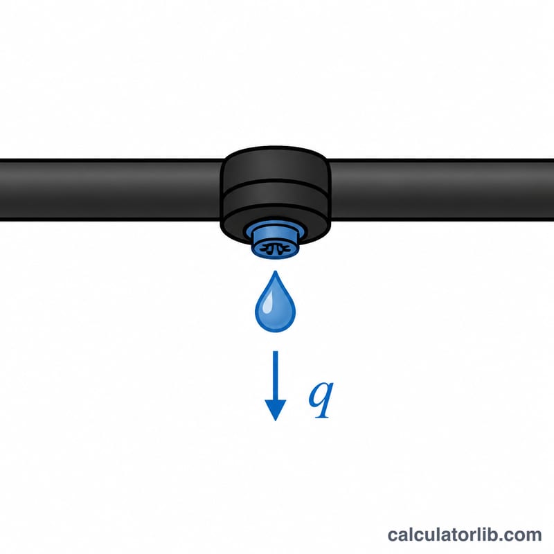
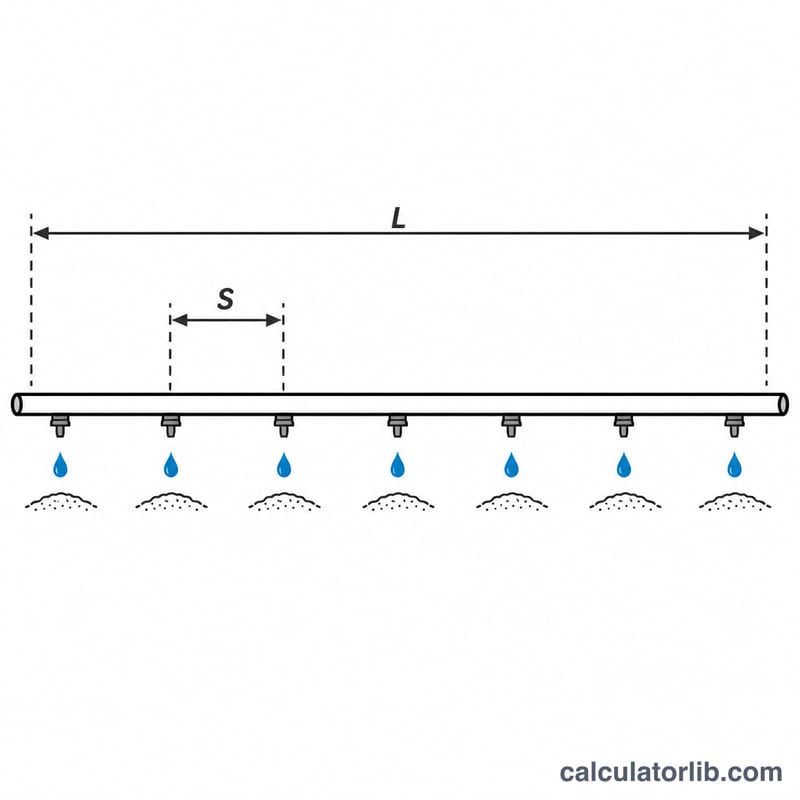
First count the emitters, then multiply by each emitter output. With \(L\) = line length, \(S\) = emitter spacing, and \(q\) = per-emitter flow rate, the emitter count and total flow are:
$$N = \left\lfloor \frac{L}{S} \right\rfloor + 1, \qquad Q = N \times q$$Here \(N\) is the number of emitters (one at each end is included, hence the \(+1\)) and \(Q\) is the total line flow. Keep \(L\) and \(S\) in the same length unit so the ratio is dimensionless.
How to use it
Enter the length of the lateral in meters, the spacing between emitters in meters, and the rated output of one emitter in liters per hour. The calculator returns the emitter count, the total flow in liters per hour, and the equivalent in US gallons per hour using \(1\,\text{L} = 0.264172\,\text{gal}\).
Worked example
Suppose a lateral is \(100\,\text{m}\) long with emitters every \(0.5\,\text{m}\), each rated at \(2\,\text{L/h}\):
$$N = \left\lfloor \frac{100}{0.5} \right\rfloor + 1 = 201$$$$Q = 201 \times 2 = 402\,\text{L/h}$$That is about \(402 \times 0.264172 \approx 106.2\,\text{gal/h}\) — a useful figure when checking your pump and mainline capacity.
FAQ
Why add one to the count? A line of length \(L\) with spacing \(S\) has emitters at both ends, so it holds \(\lfloor L/S \rfloor + 1\) emitters, not just \(L/S\).
Does emitter flow stay constant? Pressure-compensating emitters hold a near-constant rate over a wide pressure range; non-compensating emitters vary with pressure, so use their rated flow at your operating pressure.
Can I plan a whole zone? Yes — compute each lateral, then sum the flows to size the zone valve and supply line.