What is three-phase Ohm's law?
Ohm's law links voltage, current and resistance, but in a balanced three-phase system you must also account for the phase angle between voltage and current and for the way the load is connected. This calculator solves a balanced three-phase circuit for real power, line current, line-to-line voltage or per-phase impedance and resistance.
How to use it
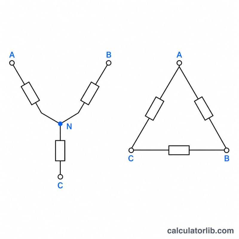
Choose what to solve for, pick a wye (Y) or delta (Δ) connection, then enter the other known values: line-to-line voltage in volts, line current in amps, real power in kW and the power factor. The field for the quantity you solve for is ignored. Results also show apparent power, reactive power, phase voltage and current, and the resistance and reactance of each phase.
The formulas
Real power of a balanced load is:
$$P = \sqrt{3}\, V_L I_L \cos\varphi$$where \(V_L\) is the line-to-line voltage, \(I_L\) the line current and \(\cos\varphi\) the power factor. Current and voltage follow by rearranging. For a wye load \(V_{ph} = V_L/\sqrt{3}\) and \(I_{ph} = I_L\); for a delta load \(V_{ph} = V_L\) and \(I_{ph} = I_L/\sqrt{3}\). Then \(Z_{ph} = V_{ph}/I_{ph}\), \(R = Z_{ph}\cos\varphi\) and \(X = Z_{ph}\sin\varphi\).
Worked example
A 400 V wye load draws 10 A at a power factor of 0.8.
$$P = \sqrt{3} \times 400 \times 10 \times 0.8 = 5542.6\,\text{W} \approx 5.54\,\text{kW}$$$$Z_{ph} = \frac{400/\sqrt{3}}{10} = 23.09\,\Omega, \quad R = 23.09 \times 0.8 = 18.48\,\Omega$$Wye vs Delta Relationships and Common Three-Phase Voltages
For a balanced three-phase load, the line quantities (measured between supply conductors and in the supply lines) relate to the per-phase quantities (across or through each load element) differently for wye (star) and delta (mesh) connections. In both cases real power is \(P = \sqrt{3}\,V_L I_L \cos\varphi\).
| Quantity | Wye (Y) | Delta (Δ) |
|---|---|---|
| Line vs phase voltage | \(V_L = \sqrt{3}\,V_{ph}\) | \(V_L = V_{ph}\) |
| Line vs phase current | \(I_L = I_{ph}\) | \(I_L = \sqrt{3}\,I_{ph}\) |
| Phase impedance | \(Z_{ph} = \dfrac{V_L}{\sqrt{3}\,I_L}\) | \(Z_{ph} = \dfrac{\sqrt{3}\,V_L}{I_L}\) |
Common three-phase line-to-line voltages and the corresponding wye phase (line-to-neutral) voltage, \(V_{ph} = V_L/\sqrt{3}\):
| Line-to-line / phase (V) | Typical use |
|---|---|
| 208 / 120 | North America, commercial and light-industrial buildings |
| 380 / 220 | Older IEC-style systems in parts of Europe and Asia |
| 400 / 230 | Europe and other IEC (50 Hz) regions, current standard |
| 415 / 240 | UK legacy, Australia and other regions using the older nominal value |
| 480 / 277 | North America (US), industrial and large commercial |
| 600 / 347 | Canada, industrial |
Phase voltages are rounded nominal values (for example 400/√3 ≈ 230.9 V, nominally 230 V). Actual systems and tolerances vary by country and utility.
Comparing Results at Different Power Factors and Connections
The table fixes the line voltage at 400 V and the line current at 10 A. Apparent power is \(S = \sqrt{3}\cdot 400\cdot 10 = 6928.2\) VA ≈ 6.93 kVA. Real power is \(P = S\cos\varphi\) and reactive power is \(Q = S\sin\varphi\).
| Power factor | Real power P (kW) | Apparent power S (kVA) | Reactive power Q (kvar) |
|---|---|---|---|
| 1.0 | 6.93 | 6.93 | 0.00 |
| 0.9 | 6.24 | 6.93 | 3.02 |
| 0.8 | 5.54 | 6.93 | 4.16 |
| 0.6 | 4.16 | 6.93 | 5.54 |
Example (PF 0.8): \(P = \dfrac{\sqrt{3}\cdot 400\cdot 10\cdot 0.8}{1000} = 5.54\) kW, and \(Q = 6.93\cdot 0.6 = 4.16\) kvar.
| Connection | Phase impedance formula | Substitution | Zph (Ω) |
|---|---|---|---|
| Wye | \(V_L/(\sqrt{3}\,I_L)\) | \(400/(1.732\cdot 10)\) | 23.09 |
| Delta | \(\sqrt{3}\,V_L/I_L\) | \(1.732\cdot 400/10\) | 69.28 |
The same line voltage and current require a delta phase impedance three times that of a wye phase (69.28 ≈ 3 × 23.09). The impedance magnitude does not depend on power factor; PF only sets how the current is split between real and reactive parts.
Key Terms and Symbols
- Line-to-line voltage (VL, V): the voltage between any two line conductors of a three-phase system.
- Phase voltage (Vph, V): the voltage across a single load element (winding or impedance); in wye it equals VL/√3, in delta it equals VL.
- Line current (IL, A): the current in each supply conductor.
- Phase current (Iph, A): the current through a single load element; equals IL in wye and IL/√3 in delta.
- Real power (P, W): the power actually converted to work or heat; \(P = \sqrt{3}\,V_L I_L\cos\varphi\).
- Reactive power (Q, var): power exchanged back and forth with inductive or capacitive elements; \(Q = \sqrt{3}\,V_L I_L\sin\varphi\).
- Apparent power (S, VA): the product \(S = \sqrt{3}\,V_L I_L\), with \(S^2 = P^2 + Q^2\).
- Power factor (PF, dimensionless): \(\cos\varphi = P/S\), between 0 and 1 (lagging for inductive, leading for capacitive loads).
- Impedance (Z, Ω): total opposition to AC current per phase, \(Z = \sqrt{R^2 + X^2}\).
- Resistance (R, Ω): the real part of impedance, \(R = Z\cos\varphi\).
- Reactance (X, Ω): the imaginary part of impedance from inductance or capacitance, \(X = Z\sin\varphi\).
- Wye (star, Y): connection with the three load elements joined at a common neutral point.
- Delta (Δ): connection with the three load elements joined in a closed triangle, with no neutral point.
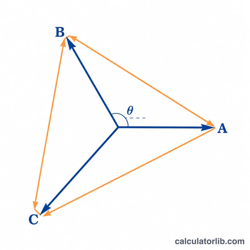
- Balanced load: a load with identical impedance in all three phases, giving equal-magnitude currents and voltages displaced by 120°; the formulas on this page assume it.
FAQ
Does this work for unbalanced loads?
No. It assumes all three phases carry equal currents and have identical impedance.
Why is the square root of 3 used?
Line voltage is the phasor difference of two phase voltages 120 degrees apart, which makes it \(\sqrt{3}\) times larger than the phase voltage in a wye system.
What if my power factor is 1?
The load is purely resistive, so impedance equals resistance and reactive power is zero.