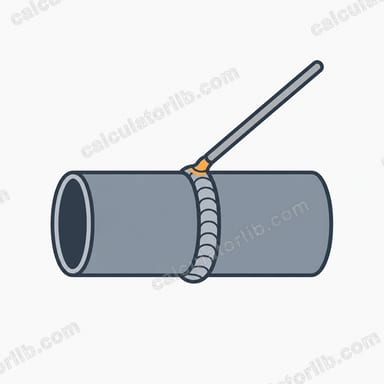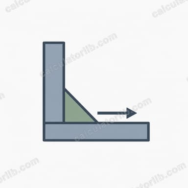
What is a fillet weld stress calculator?
A fillet weld joins two surfaces at roughly right angles, such as a bracket welded to a plate. This calculator estimates the average shear stress in the weld when a load acts along or across it, using the common simplified throat method. It is a quick design check, not a replacement for a code-compliant calculation by a qualified engineer.
How to use it
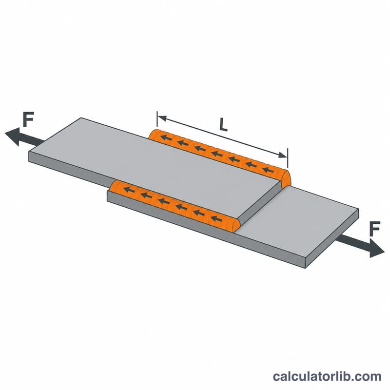
Enter the applied load in newtons, the weld leg size in millimetres, the length of each weld run and the number of weld lines (a lap joint welded on both sides has 2). Then enter the allowable shear stress for your weld metal and design code. The tool returns the shear stress, throat area, safety factor and utilization.
The formula explained
For an equal-leg 45° fillet weld, the effective throat is \(t = a\cos 45^\circ \approx 0.7071\,a\), where \(a\) is the leg size. The stress is the load divided by the total throat area:
$$\tau = \frac{F}{0.7071 \times a \times L \times n}$$Here \(F\) = load in N, \(L\) = length of each weld in mm and \(n\) = number of weld lines. The safety factor is \(SF = \tau_{\text{allow}} / \tau\).

Worked example
A 50,000 N load is carried by two 100 mm long fillet welds with a 6 mm leg. The throat is \(0.7071 \times 6 = 4.243\) mm, so the area is:
$$A = 4.243 \times 100 \times 2 = 848.5\,\text{mm}^2$$$$\tau = \frac{50000}{848.5} = 58.93\,\text{MPa}$$With an allowable stress of 145 MPa, \(SF = 145 / 58.93 = 2.46\) and utilization is about 40.6%.
Typical Allowable Shear Stress by Electrode Class
The table lists common SMAW (stick) electrode classes with their minimum tensile strength \(F_{EXX}\) and the allowable weld shear stress under the AISC ASD (US) approach for fillet welds, \(0.30 \times F_{EXX}\).
| Electrode class | Min. tensile strength (ksi) | Min. tensile strength (MPa) | Allowable weld shear, 0.30 × FEXX (MPa) |
|---|---|---|---|
| E60xx | 60 | 414 | about 124 |
| E70xx | 70 | 482 | about 145 |
| E80xx | 80 | 551 | about 165 |
The 145 MPa allowable used in the worked examples and scenario table corresponds to an E70xx electrode (0.30 × 482 ≈ 145 MPa).
These values are illustrative. The governing code, specification or project requirement and its safety factor always take precedence. LRFD (AISC) and Eurocode 3 use different resistance factors and different weld strength formulas, so their design values cannot be read directly from this table.
Interpreting Safety Factor and Utilization
The calculator compares the average shear stress on the weld throat with the allowable stress you enter:
$$\text{SF} = \frac{\tau_{\text{allow}}}{\tau}, \qquad \text{Utilization} = \frac{\tau}{\tau_{\text{allow}}} = \frac{1}{\text{SF}}$$
- SF > 1 (utilization < 100%): the weld passes the check against the allowable stress.
- SF ≈ 1 (utilization ≈ 100%): the weld is right at the allowable limit, with no margin for uncertainty.
- SF < 1 (utilization > 100%): the weld is overstressed relative to the allowable value.
Allowable stress usually already contains a design factor (about 2 for AISC ASD), so this SF is relative to the allowable stress, not to the ultimate strength of the weld. An SF of 1.5 here does not mean 1.5 times the failure load.
The result covers direct shear on the throat only, assuming the load is spread evenly over the weld length. Fatigue, eccentric or combined loading (bending, torsion), and the strength of the base metal must be checked separately. This tool is a quick estimate and not a substitute for a design review under the applicable code.
How Leg Size and Weld Length Affect Stress
All rows use F = 50,000 N, an allowable stress of 145 MPa, throat \(t = 0.7071 \times \text{leg}\), and \(A = t \times L \times n\), where \(n\) is the number of weld lines.
| Leg (mm) | Length (mm) | Weld lines n | Throat area (mm²) | Shear stress (MPa) | SF | Utilization |
|---|---|---|---|---|---|---|
| 4 | 50 | 1 | 141.4 | 353.55 | 0.41 | 243.8% |
| 4 | 100 | 1 | 282.8 | 176.78 | 0.82 | 121.9% |
| 4 | 100 | 2 | 565.7 | 88.39 | 1.64 | 61.0% |
| 6 | 50 | 2 | 424.3 | 117.85 | 1.23 | 81.3% |
| 6 | 100 | 1 | 424.3 | 117.85 | 1.23 | 81.3% |
| 6 | 100 | 2 | 848.5 | 58.93 | 2.46 | 40.6% |
| 6 | 150 | 2 | 1272.8 | 39.28 | 3.69 | 27.1% |
| 8 | 100 | 2 | 1131.4 | 44.19 | 3.28 | 30.5% |
| 8 | 150 | 1 | 848.5 | 58.93 | 2.46 | 40.6% |
Worked check for the 6 mm, 100 mm, n = 2 row: \(t = 0.7071 \times 6 = 4.2426\) mm, \(A = 4.2426 \times 100 \times 2 = 848.5\) mm², \(\tau = 50{,}000 / 848.5 = 58.93\) MPa, and \(\text{SF} = 145 / 58.93 = 2.46\).
Stress is inversely proportional to leg size, weld length and number of weld lines: doubling any one of them halves the stress and doubles the SF. Several rows with the same total throat area (for example 6 mm × 100 mm × 1 and 6 mm × 50 mm × 2) give identical results.
FAQ
Does this include bending or torsion?
No. It assumes the load is shared uniformly over the weld throat area (direct shear). Eccentric loads create bending or torsion that need extra analysis.
What allowable stress should I use?
It depends on the filler metal and the design code, commonly about 30% of the electrode tensile strength in older practice. Always confirm with your governing standard.
Why is the throat used instead of the leg?
Failure normally occurs through the shortest section of the weld, the throat, which is smaller than the leg size.