What Is AC Power?
In alternating-current (AC) circuits, power splits into three related quantities. Real power (P), measured in watts (W), is the power actually converted into useful work or heat. Reactive power (Q), measured in volt-amps reactive (VAR), bounces back and forth between source and reactive components (inductors and capacitors) without doing net work. Apparent power (S), measured in volt-amps (VA), is the product of RMS voltage and current — the total the supply must deliver.
How to Use This Calculator
Enter the RMS voltage, the RMS current, and the power factor (cos φ, between 0 and 1). The calculator returns real, reactive and apparent power, plus the phase angle \(\varphi\). Use a power factor of 1 for a purely resistive load, and lower values as the load becomes more inductive or capacitive.
The Formulas Explained
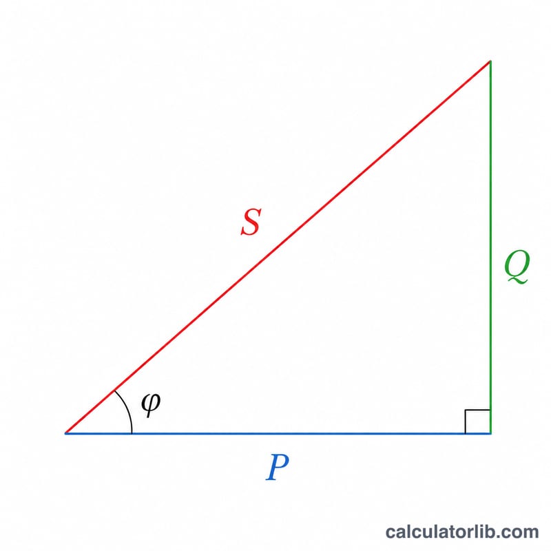
These quantities form the "power triangle": \(S^2 = P^2 + Q^2\). The power factor is the cosine of the phase angle between voltage and current. From it the reactive component is found with \(\sin\varphi = \sqrt{1 - \cos^2\varphi}\). So:
$$P = V \cdot I \cdot \cos\varphi \quad Q = V \cdot I \cdot \sin\varphi \quad S = V \cdot I$$
Worked Example
For V = 230 V, I = 10 A and power factor = 0.8: apparent power \(S = 230 \times 10 = 2300\) VA. Real power \(P = 2300 \times 0.8 = 1840\) W. With \(\sin\varphi = \sqrt{1 - 0.64} = 0.6\), reactive power \(Q = 2300 \times 0.6 = 1380\) VAR, and the phase angle \(\varphi = \arccos(0.8) \approx 36.87°\).
Typical Power Factors of Common Loads
Power factor (PF) describes how effectively a load converts apparent power (VA) into useful real power (W). Purely resistive loads have a PF near 1.0, while inductive loads (motors, transformers, ballasts) draw additional reactive power and have a PF below 1.0. The values below are typical ranges for single-phase loads; the actual figure depends on load level, design and operating conditions.
| Load type | Typical power factor | Nature |
|---|---|---|
| Incandescent lamps / resistive heaters | ≈ 1.0 | Resistive |
| LED lighting (good drivers) | 0.90 – 0.95 | Slightly capacitive/non-linear |
| Fluorescent lighting | 0.50 – 0.90 | Inductive (magnetic ballast) to corrected |
| Induction motor (fully loaded) | 0.80 – 0.90 | Lagging (inductive) |
| Induction motor (unloaded / lightly loaded) | 0.20 – 0.40 | Lagging (inductive) |
| Distribution transformer (lightly loaded) | 0.30 – 0.70 | Lagging (magnetizing current) |
| Computers / switch-mode power supplies (uncorrected) | 0.55 – 0.75 | Non-linear |
| Computers / SMPS with active PFC | 0.95 – 0.99 | Corrected non-linear |
| Refrigerator / compressor motors | 0.60 – 0.80 | Lagging (inductive) |
| Welding equipment (arc) | 0.50 – 0.70 | Lagging |
Low power factor increases the current required to deliver a given real power, raising conductor losses and the apparent power (VA) the supply must provide.
Definitions & Glossary
- Real power (P)
- The power actually converted into useful work or heat, measured in watts (W). \(P = S\cdot\text{PF} = V I \cos\varphi\). This is what most utility energy meters bill.
- Reactive power (Q)
- Power that oscillates between source and reactive components (inductors, capacitors) without doing net work, measured in volt-amperes reactive (VAR). \(Q = V I \sin\varphi\). It is positive for lagging (inductive) and negative for leading (capacitive) loads.
- Apparent power (S)
- The product of RMS voltage and RMS current, measured in volt-amperes (VA). \(S = V I = \sqrt{P^2 + Q^2}\). It sets the rating of cables, transformers and generators.
- Power factor (PF)
- The ratio of real power to apparent power, \(\text{PF} = P/S = \cos\varphi\), ranging from 0 to 1. A PF of 1.0 means all supplied power does useful work.
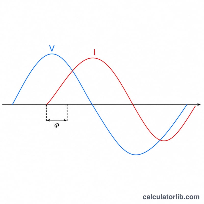
- Phase angle (φ)
- The angle between the voltage and current waveforms, \(\varphi = \cos^{-1}(\text{PF})\). For a purely resistive load \(\varphi = 0\); for purely reactive loads it approaches ±90°.
- RMS voltage
- Root-mean-square voltage — the equivalent DC voltage that delivers the same heating power. For a sinusoid, \(V_{\text{rms}} = V_{\text{peak}}/\sqrt{2}\). AC ratings (e.g. 120 V, 230 V) are RMS values.
- RMS current
- Root-mean-square current, the equivalent DC current producing the same heating effect; used in all AC power calculations.
- Leading vs lagging power factor
- Lagging: current lags voltage, typical of inductive loads such as motors and transformers (Q positive). Leading: current leads voltage, typical of capacitive loads and over-corrected systems (Q negative).
FAQ
Is this for single-phase or three-phase? It uses the single-phase formula \(S = V \cdot I\). For three-phase balanced loads, multiply by \(\sqrt{3}\) using line values.
What does a power factor below 1 mean? It indicates reactive loading (motors, transformers). Lower PF means more current is needed to deliver the same real power.
What is the phase angle? It is the angle between voltage and current waveforms, equal to \(\arccos(\text{power factor})\).