What Is Signal Attenuation?
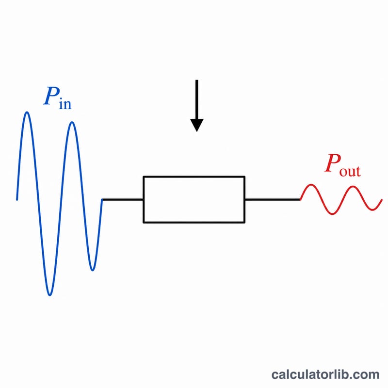
Signal attenuation is the loss of signal strength as power travels through a medium such as a cable, fiber, connector, or free space. It is measured in decibels (dB), a logarithmic unit that conveniently expresses very large ratios in small, easy-to-read numbers. A positive attenuation value means the output power is lower than the input power — the signal has weakened.
How to Use This Calculator
Enter the input power (\(P_{in}\)) and the output power (\(P_{out}\)) in the same unit — milliwatts (mW) is used here, but any consistent power unit works because the result depends only on the ratio. Click calculate and the tool returns the attenuation in decibels along with the raw power ratio. This is useful for evaluating cable runs, splitters, attenuator pads, and overall link budgets.
The Formula Explained
The attenuation in decibels is given by:
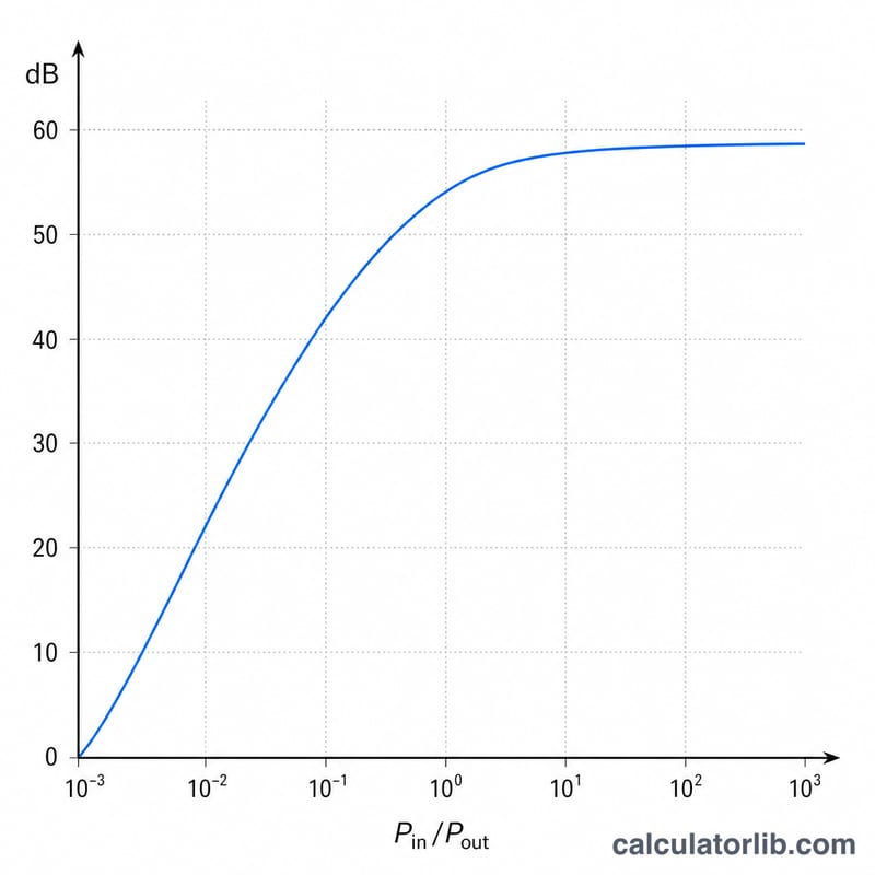
$$\text{Attenuation (dB)} = 10 \cdot \log_{10}\!\left(\frac{\text{Input Power (mW)}}{\text{Output Power (mW)}}\right)$$
Because power scales as the square of voltage or current, the power form uses a factor of 10. (If you were working with voltage or current ratios instead, the factor would be 20.) The base-10 logarithm compresses a wide dynamic range: a 10× power loss is 10 dB, a 100× loss is 20 dB, and a 1000× loss is 30 dB.
Worked Example
Suppose a signal enters a cable at 100 mW and exits at 10 mW. The power ratio is \(100 / 10 = 10\). The attenuation is $$10 \times \log_{10}(10) = 10 \times 1 = 10 \text{ dB}.$$ The signal lost 90% of its power, expressed compactly as a 10 dB loss.
Typical Attenuation Values for Common Media
Attenuation depends strongly on frequency, cable type, and—for fiber—wavelength. The values below are representative, widely-documented figures useful for first-pass planning. Always confirm against the manufacturer datasheet for the exact part and frequency you are using, since loss rises with frequency for copper and varies by wavelength for fiber.
Coaxial cable (loss per 100 m)
| Cable | Frequency | Approx. loss |
|---|---|---|
| RG-58 | 100 MHz | ~16 dB/100 m |
| RG-58 | 400 MHz | ~33 dB/100 m |
| RG-6 | 100 MHz | ~6 dB/100 m |
| RG-6 | 1000 MHz | ~20 dB/100 m |
Twisted-pair (Cat5e / Cat6, per 100 m channel)
| Cable | Frequency | Approx. insertion loss |
|---|---|---|
| Cat5e | 100 MHz | ~22 dB/100 m |
| Cat6 | 100 MHz | ~20 dB/100 m |
| Cat6 | 250 MHz | ~33 dB/100 m |
Optical fiber (loss per km)
| Fiber / wavelength | Approx. loss |
|---|---|
| Single-mode @ 1310 nm | ~0.32–0.4 dB/km |
| Single-mode @ 1550 nm | ~0.17–0.25 dB/km |
| Multimode (OM3/OM4) @ 850 nm | ~2.5–3.0 dB/km |
| Multimode @ 1300 nm | ~0.7–1.0 dB/km |
Connector and splitter insertion loss
| Component | Typical loss |
|---|---|
| Fiber connector (mated pair, LC/SC) | ~0.3–0.75 dB |
| Fusion splice | ~0.1 dB |
| Mechanical splice | ~0.3 dB |
| Optical 2-way splitter (1×2) | ~3.5 dB |
| Optical 4-way splitter (1×4) | ~7.2 dB |
| Optical 8-way splitter (1×8) | ~10.5 dB |
| RF coax connector (N, SMA) | ~0.1–0.3 dB |
FAQ
Does it matter what unit of power I use? No. Since the formula uses a ratio of two powers, any consistent unit (mW, W, µW) gives the same dB result, as long as both inputs share the unit.
What does a negative result mean? A negative value means the output power exceeds the input power — i.e. gain rather than loss, which happens with amplifiers.
Why use decibels instead of a plain ratio? Decibels turn multiplication of ratios into addition, making it easy to add up the losses of multiple components in a chain to get the total link loss.