What Is Capacitive Reactance?
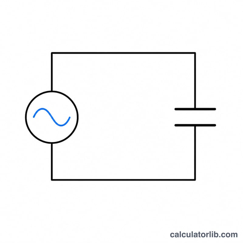
Capacitive reactance (Xc) is the opposition that a capacitor presents to alternating current (AC). Unlike a resistor, a capacitor's opposition depends on the signal frequency: the higher the frequency, the lower the reactance. Reactance is measured in ohms (Ω), just like resistance, but it does not dissipate energy as heat — it stores and releases it.
How to Use This Calculator
Enter the AC frequency in hertz (Hz) and the capacitance value in microfarads (µF). The calculator converts microfarads to farads automatically and returns the capacitive reactance in ohms. Use it for filter design, coupling/decoupling networks, and AC circuit analysis.
The Formula Explained
The reactance is given by \(X_C = \dfrac{1}{2\pi f C}\), where f is frequency in hertz and C is capacitance in farads. The constant \(2\pi\) converts frequency to angular frequency (\(\omega = 2\pi f\)). As f or C increases, the product in the denominator grows and Xc falls — which is why capacitors pass high frequencies and block DC (0 Hz gives infinite reactance).
$$X_C = \frac{1}{2\pi \cdot \text{Frequency (Hz)} \cdot \text{Capacitance (µF)} \times 10^{-6}}$$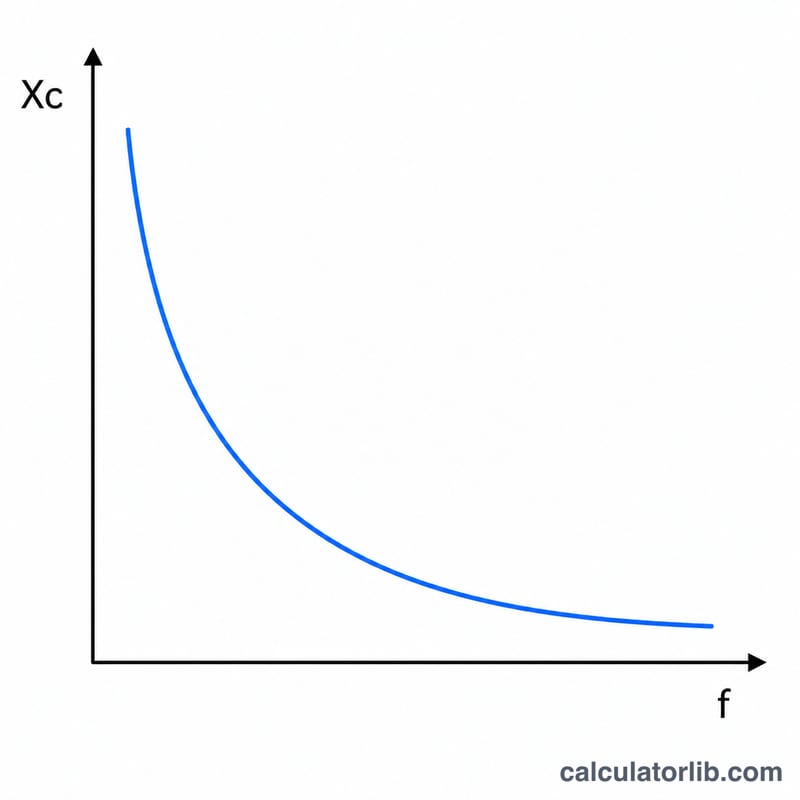
Worked Example
For a 10 µF capacitor at 60 Hz: \(C = 10 \times 10^{-6} = 0.00001 \ \text{F}\). Then $$X_C = \frac{1}{2 \times \pi \times 60 \times 0.00001} = \frac{1}{0.0037699} \approx 265.26 \ \Omega.$$ At 1000 Hz the same capacitor would have only \(\approx 15.9 \ \Omega\) of reactance.
Interpreting Your Xc Result
Capacitive reactance \(X_C\) is the opposition, in ohms, that a capacitor presents to alternating current at one particular frequency. It is inversely proportional to both frequency and capacitance. If you double either one, \(X_C\) halves. Here is how to read the number in a real circuit.
Current and phase in an ideal capacitor
In an ideal capacitor the current leads the voltage by exactly 90°. The RMS current follows a form of Ohm's law that uses reactance instead of resistance:
$$I = \frac{V}{X_C}$$For example, a 1 µF capacitor at 1,000 Hz has
$$X_C = \frac{1}{2\pi \times 1000 \times 1\times 10^{-6}} = \frac{1}{0.0062832} \approx 159.15\ \Omega$$which gives 159.15 Ω. With 10 V RMS across it, the RMS current is \(I = 10 / 159.15 \approx 0.0628\) A, or about 62.8 mA. Because current and voltage are 90° out of phase, an ideal capacitor stores energy and returns it each cycle. It dissipates no average (real) power.
Series RC circuits: impedance and phase angle
When a resistor \(R\) is in series with the capacitor, reactance and resistance do not simply add. They combine as perpendicular components:
$$Z = \sqrt{R^2 + X_C^2}$$$$\theta = -\arctan\left(\frac{X_C}{R}\right)$$The negative phase angle means the circuit voltage lags the current, which is the capacitive behaviour. If \(X_C \gg R\), \(\theta\) approaches −90° and the circuit behaves almost like a pure capacitor. If \(X_C \ll R\), \(\theta\) approaches 0° and it behaves almost like a pure resistor.
The cutoff frequency: where Xc = R
The frequency at which \(X_C\) equals \(R\) is the cutoff (corner) frequency:
$$f_c = \frac{1}{2\pi R C}$$At \(f_c\) the impedance is \(Z = \sqrt{2}\,R\) and the phase angle is −45°. This is the −3 dB point of both first-order RC low-pass and RC high-pass filters, where the output voltage falls to about 70.7% (\(1/\sqrt{2}\)) of the passband level. If you compare your \(X_C\) result with the resistor in your circuit, you can tell which side of the cutoff you are on. \(X_C > R\) means you are below \(f_c\), and \(X_C < R\) means you are above it.
Rough guide: short, open, or in between?
- \(X_C\) much smaller than the surrounding circuit impedance (a common rule of thumb is under about one-tenth): the capacitor acts close to a short circuit at that frequency. This is usually the goal for coupling capacitors, which pass the AC signal between stages, and for bypass and decoupling capacitors, which shunt noise to ground.
- \(X_C\) much larger than the surrounding impedance: the capacitor acts close to an open circuit, so it blocks that frequency. At DC (0 Hz), \(X_C\) is effectively infinite.
- \(X_C\) comparable to the surrounding impedance: the capacitor significantly shapes amplitude and phase. This is the region where filters and timing networks do their work.
Limits of the ideal formula
The formula \(X_C = 1/(2\pi f C)\) describes an ideal capacitor. Real capacitors also have equivalent series resistance (ESR) and equivalent series inductance (ESL), which comes from the leads, terminations and internal construction. ESL resonates with the capacitance at the self-resonant frequency (SRF). Near the SRF the measured impedance falls to a minimum set by the ESR. Above the SRF the part behaves inductively, and its impedance rises with frequency instead of continuing to fall as \(1/(2\pi f C)\) predicts. For high-frequency decoupling or RF work, check the manufacturer's impedance-vs-frequency curve and don't rely on the calculated \(X_C\) alone.
FAQ
Why does reactance decrease with frequency? A capacitor charges and discharges more readily as the signal alternates faster, so it impedes the current less.
What is the reactance at DC? At 0 Hz the denominator is zero, giving infinite reactance — a capacitor blocks DC.
What units should I use? Enter frequency in Hz and capacitance in µF; the result is in ohms. For nanofarads divide by 1000 to convert to µF, or for picofarads divide by 1,000,000.