What this calculator does
Air conditioning and heating systems only work well when every room gets its fair share of air. This tool converts a room size into a required airflow in cubic feet per minute (CFM), then tells you how many supply registers and what round duct diameter will carry that air. It uses imperial units (feet, CFM, BTU/h, ft/min) as used in the United States and Canada; metric designers can convert with \(1\,\text{CFM} = 1.699\,\text{m}^3/\text{h}\).
How to use it
Enter the room length, width and ceiling height, then pick a sizing method. The ACH method targets a number of complete air changes per hour (4-6 for bedrooms and living rooms, 6-8 for kitchens, 8-10 for bathrooms). The CFM per square foot method applies a flat rule of thumb, usually about 1.0. The load share method is the most accurate: it splits the measured blower airflow in proportion to each room heating or cooling load from a Manual J style calculation. Finally set the maximum CFM you want per register and the duct design velocity (500-700 ft/min keeps branch runs quiet).
The formula explained
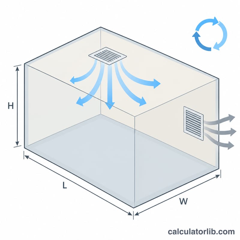
With \(L\), \(W\) and \(H\) in feet, the room volume is \(V = L \times W \times H\). Because ACH is expressed per hour and CFM per minute, the volume is divided by 60:
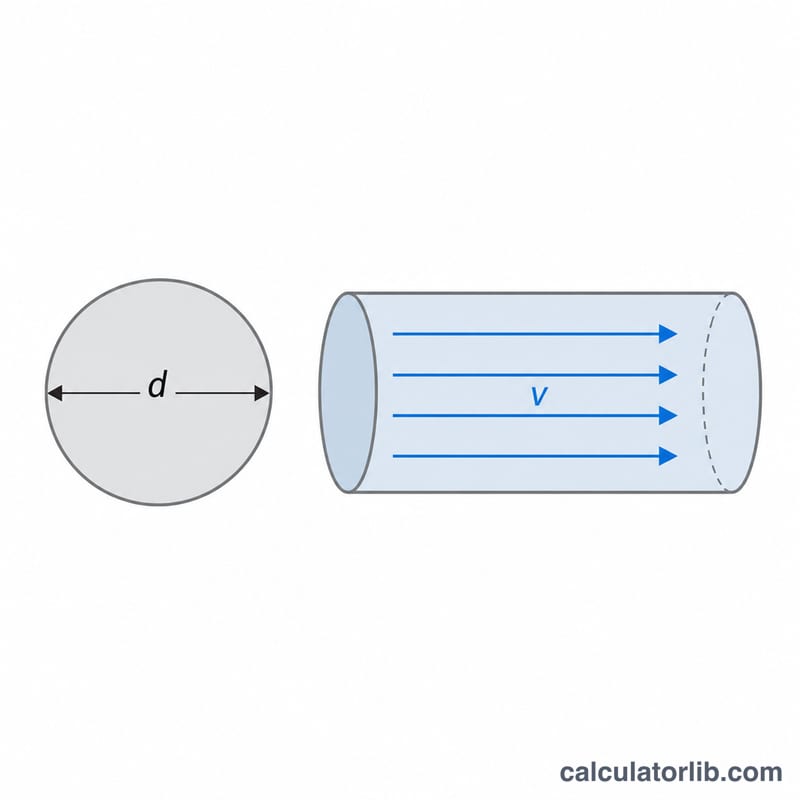
$$\text{CFM} = \frac{L \times W \times H \times \text{ACH}}{60}$$The duct size comes from the continuity relation \(A = \text{CFM}/V_{air}\), where \(A\) is the cross-section in square feet. Converting that circle to a diameter in inches gives \(d = 12\sqrt{4A/\pi}\).
Worked example
A 12 ft by 14 ft bedroom with a 9 ft ceiling at 6 ACH:
$$V = 12 \times 14 \times 9 = 1512\,\text{ft}^3$$ $$\text{CFM} = \frac{1512 \times 6}{60} = 151.2$$At 700 ft/min the branch duct needs
$$d = 12\sqrt{\frac{4 \times (151.2/700)}{\pi}} = 6.29\,\text{in}$$so a 7 inch round duct and two 100 CFM registers will serve the room.
Round Duct Size and Register Capacity by CFM
Once the calculator returns a room's required airflow, the next question is what carries it. Duct capacity follows directly from the continuity relationship \(\text{CFM} = A \times V\), where \(A\) is the cross-sectional area in square feet and \(V\) is the design velocity in feet per minute. For round duct of diameter \(d\) in inches:
$$A = \frac{\pi d^2}{4 \times 144}\ \text{ft}^2 \qquad\Longrightarrow\qquad \text{CFM} = \frac{\pi d^2}{576} \times V$$Table 1 — Maximum airflow for standard round duct at three design velocities. The 600 and 700 ft/min columns are the usual branch-duct range; 900 ft/min is near the upper limit for a main trunk. Values are computed, not rounded to a catalog.
| Duct diameter (in) | Area (ft²) | CFM at 600 ft/min (branch) | CFM at 700 ft/min (branch) | CFM at 900 ft/min (trunk) |
|---|---|---|---|---|
| 4 | 0.087 | 52 | 61 | 79 |
| 5 | 0.136 | 82 | 95 | 123 |
| 6 | 0.196 | 118 | 137 | 177 |
| 7 | 0.267 | 160 | 187 | 241 |
| 8 | 0.349 | 209 | 244 | 314 |
| 9 | 0.442 | 265 | 309 | 398 |
| 10 | 0.545 | 327 | 382 | 491 |
| 12 | 0.785 | 471 | 550 | 707 |
| 14 | 1.069 | 641 | 748 | 962 |
| 16 | 1.396 | 838 | 977 | 1257 |
Table 2 — Common supply register and grille face sizes. Capacity is based on an effective free area of roughly 70% of the nominal face area (typical for a stamped or bar-type face; bar grilles run higher, heavily louvered stamped faces lower) at 500–700 ft/min face velocity. Throw figures are approximate and depend heavily on vane setting, supply temperature and mounting position — always confirm against the manufacturer's published performance data, which is also the only reliable source for sound (NC) ratings.
| Nominal face size (in) | Nominal area (in²) | Assumed free area (in²) | CFM at 500 ft/min | CFM at 700 ft/min | Approx. throw (ft) |
|---|---|---|---|---|---|
| 4 × 10 | 40 | 28 | 95 | 135 | 6–10 |
| 4 × 12 | 48 | 34 | 115 | 165 | 7–11 |
| 6 × 10 | 60 | 42 | 145 | 205 | 8–12 |
| 10 × 6 | 60 | 42 | 145 | 205 | 8–12 |
| 6 × 12 | 72 | 50 | 175 | 245 | 9–14 |
| 8 × 14 | 112 | 78 | 270 | 380 | 12–18 |
Two corrections matter before you commit to a size:
- Flexible duct carries less. Because of the helical wire and inner-liner wrinkles, flex duct has noticeably higher friction than smooth galvanized pipe of the same nominal diameter — plan on roughly 10–15% less airflow for the same pressure drop, and considerably worse than that if the flex is compressed, sagging between supports, or routed with tight bends. Pull flex taut and use long-radius turns.
- Velocity alone is not a size. Table 1 answers "what fits" but not "what the blower can push." A complete design sizes every run against a friction rate, commonly about 0.08–0.10 in w.g. per 100 ft of equivalent length for typical residential systems, derived from the available static pressure and the total effective length of the longest supply and return path. A duct that passes the velocity check can still starve a room if the fittings on its path add enough equivalent length. Velocity and friction rate are both limits; the duct must satisfy whichever is stricter.
Applying the Result in a Real Duct Layout
Work a bedroom through end to end. For a 14 ft × 12 ft room with an 8 ft ceiling at 6 ACH:
$$V = 14 \times 12 \times 8 = 1344\ \text{ft}^3$$$$\text{CFM}_{\text{room}} = \frac{1344 \times 6}{60} = 134.4\ \text{CFM}$$$$d = 12\sqrt{\frac{4 \times 134.4}{\pi \times 600}} = 12\sqrt{0.2852} = 6.41\ \text{in}$$So the room needs 134.4 CFM, a theoretical 6.41 in duct, and — at a 100 CFM-per-register limit — two registers. Here is how that becomes an installed layout.
- Round the diameter up, never down. 6.41 in becomes a 7 in branch, not a 6 in one. A 6 in duct at 600 ft/min carries only about 118 CFM, so rounding down would short the room by roughly 12% before a single fitting is counted. Rounding up costs a little more sheet metal and buys back pressure drop.
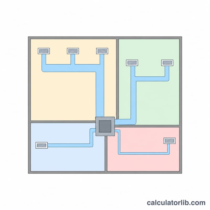
- Split the supply once the room exceeds roughly 100–150 CFM. Two 7 in × 134 CFM... no — two registers each handling about 67 CFM off one 7 in branch. Splitting keeps face velocity and noise down and lets you cover a long or L-shaped room. Place the outlets under windows or along exterior walls and aim the throw up the glass, so the supply air meets the cold (or hot) surface before it reaches the occupant.
- Put a balancing damper at every branch takeoff. Design airflow is a prediction; a damper is what lets you make it true. Install dampers at the trunk takeoff where they are reachable, not buried behind drywall, and mark the final position.
- Check the totals against the blower. Sum every room's CFM and compare it with the rated blower airflow. Cooling equipment is typically designed around about 400 CFM per ton, with 350–450 CFM/ton acceptable depending on climate and humidity priorities (lower for humid climates, higher for dry ones). A 3-ton system at 400 CFM/ton moves roughly 1,200 CFM, so the room total should land within about 10% of that. If your rooms add up to 1,600 CFM, the problem is the load calculation or the equipment selection, not the duct sizes.
- Give the air a way back. Supply without return just pressurizes the room and pushes the air out through the building envelope. Each closed room needs a dedicated return, a transfer grille, or a door undercut of roughly 1 in of clear gap per 100 CFM as a rule of thumb — so the 134 CFM bedroom above wants about 1.5 in of undercut on a standard door, or better, a transfer grille or jump duct.
- Measure after installation. Verify each register with an anemometer or, better, a flow hood (balometer), and check total airflow at the air handler by temperature rise or external static pressure. Field airflow regularly comes in 10–30% below design because of flex-duct compression, crushed elbows, dirty filters and leaky joints. The design figure tells you what to aim for; only a measurement tells you what you got.
- Know when the rule of thumb stops working. ACH and CFM-per-square-foot assume an ordinary room with ordinary skin. Rooms with vaulted or cathedral ceilings, large or west-facing glazing, floors over an unconditioned garage, bonus rooms inside the roof plane, or walls with three or four exterior exposures can need well over double the airflow a volume-based estimate predicts. Size those from a full room-by-room ACCA Manual J load (or the equivalent national method where you are), then use Manual D for the ducts and Manual T for the registers.
Used in that order, the calculator's output is a starting target for the branch and register, the load calculation is the authority on how much air the room really needs, and the post-install measurement is the only proof. Codes, standards and permitting requirements vary by country and jurisdiction — for equipment replacement, new ductwork or anything involving combustion appliances, have the design reviewed by a licensed HVAC contractor or engineer familiar with your local rules.
FAQ
Does the room CFM have to match the system total? Yes. Add up every room and compare with the blower rating, roughly 400 CFM per ton of cooling. If the rooms total more, the ACH targets are too aggressive.
Why do my two methods disagree? The ACH method rewards tall ceilings while the per-square-foot method ignores them. Rooms with large windows or vaulted ceilings should always be sized from an actual load calculation.
Can I use one big register instead of two? You can, but face velocity rises and so does noise. Keeping each register near 100 CFM gives better throw and quieter operation.