What the Duct Sizing Calculator Does
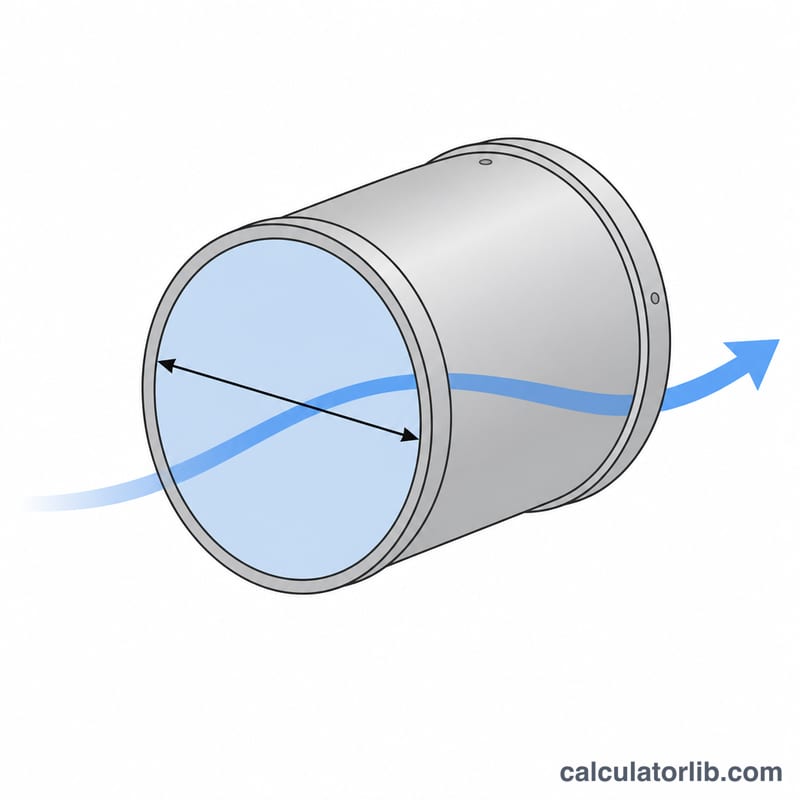
This calculator determines the round duct diameter needed to move a given airflow at a chosen design velocity. HVAC ducts must be large enough to deliver the required air volume without excessive velocity, which causes noise, high static pressure, and wasted fan energy. By entering the airflow in cubic feet per minute (CFM) and a target velocity in feet per minute (FPM), you instantly get the required cross-sectional area and equivalent round diameter.
The Formula Explained
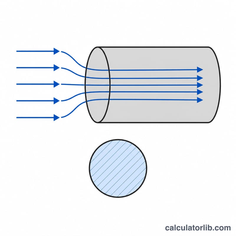
Airflow, velocity, and duct area follow the continuity relationship \(Q = A \times V\). Rearranging for the required area gives:
$$A = \frac{Q}{V}$$where \(Q\) = airflow in CFM, \(V\) = design velocity in FPM, and \(A\) = cross-sectional area in square feet. For a round duct the area relates to diameter by \(A = \frac{\pi d^2}{4}\), so solving for the diameter in feet:
$$d = \sqrt{\frac{4A}{\pi}}$$Multiply the result by 12 to convert feet to inches.
How to Use It
Enter the airflow your branch or trunk must carry and a design velocity appropriate for the application. Typical velocities are about 700-900 FPM for main supply trunks in residential systems and 500-700 FPM for branch runs to keep noise low. Higher velocities allow smaller ducts but increase pressure loss and sound.
Worked Example
Suppose a duct must carry 400 CFM at a design velocity of 800 FPM. First find the area:
$$A = \frac{400}{800} = 0.5\,\text{ft}^2$$Then the round diameter:
$$d = \sqrt{\frac{4 \times 0.5}{\pi}} = 0.798\,\text{ft} = 9.57\,\text{in}$$You would round up to the next standard size, typically a 10 inch round duct.
Standard Round Duct Sizes
Standard round sheet-metal ducts come in fixed diameters, so a computed diameter is normally rounded up to the next available size. The cross-sectional area of a round duct is fixed by geometry, \( A = \dfrac{\pi}{4}\left(\dfrac{d}{12}\right)^2 \) (with diameter \(d\) in inches, area in ft²), and the airflow it carries equals that area times the design velocity, \( \text{CFM} = A \times \text{FPM} \). The table below lists common sizes with their area and the approximate airflow at two typical design velocities (700 FPM for quiet operation and 900 FPM for a higher-velocity main). These CFM figures are purely the product of area and velocity; the actual capacity in a real system also depends on the allowable friction/pressure loss.
| Diameter (in) | Area (ft²) | Approx. CFM @ 700 FPM | Approx. CFM @ 900 FPM |
|---|---|---|---|
| 4 | 0.087 | 61 | 79 |
| 5 | 0.136 | 95 | 123 |
| 6 | 0.196 | 137 | 177 |
| 7 | 0.267 | 187 | 241 |
| 8 | 0.349 | 244 | 314 |
| 9 | 0.442 | 309 | 398 |
| 10 | 0.545 | 382 | 491 |
| 12 | 0.785 | 550 | 707 |
| 14 | 1.069 | 748 | 962 |
| 16 | 1.396 | 977 | 1257 |
| 18 | 1.767 | 1237 | 1590 |
| 20 | 2.182 | 1527 | 1964 |
Worked example: a 550 CFM supply branch designed for 700 FPM needs a diameter of \( d = 12\sqrt{\tfrac{4}{\pi}\cdot\tfrac{550}{700}} \), which works out to about 12.0 in — matching the 12 in row, so you would select a 12 in duct (or the next larger standard size if the exact value fell between two sizes).
Recommended Design Velocities
Choosing a velocity is a trade-off: lower velocities are quieter and lose less pressure but need larger ducts, while higher velocities save space but increase noise and fan energy. The ranges below reflect widely published US guidance for low-velocity systems — ACCA Manual D (residential duct design), the ASHRAE Handbook—Fundamentals, and SMACNA duct construction standards. They are typical design targets rather than absolute limits, and local codes or acoustic requirements may be stricter. Values are approximate and expressed in feet per minute (FPM).
| Application | Duct section | Low-noise range (FPM) | Higher-velocity range (FPM) |
|---|---|---|---|
| Residential | Main / trunk supply | 700–900 | up to 1000 |
| Residential | Branch supply | 600–700 | up to 800 |
| Residential | Return air (main & branch) | 500–700 | up to 800 |
| Commercial | Main / trunk supply | 1000–1500 | 1600–2000+ |
| Commercial | Branch supply | 600–1000 | up to 1600 |
| Commercial | Return air | 800–1200 | up to 1500 |
As a rule of thumb, keep supply air near occupied spaces toward the low end of these ranges to control noise, and reserve the higher velocities for main trunks in mechanical rooms or shafts where sound is less critical. Because the figures above are drawn from US design standards, verify the applicable code and manufacturer or acoustic limits for your own region before finalizing a design.
FAQ
What velocity should I use? For quiet residential systems use roughly 700-900 FPM on trunks and 500-700 FPM on branches; commercial systems tolerate higher values.
Can I use this for rectangular ducts? The result gives the equivalent round diameter. Convert it to a rectangular size with an equivalent-diameter chart while keeping the same cross-sectional area.
Why round up the size? Standard ducts come in fixed sizes, and choosing the next larger size lowers velocity, noise, and static pressure.