What is a gravity pipe flow rate calculator?
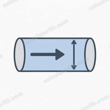
A gravity pipe flows without a pump: water moves downhill because the pipe is sloped. Storm drains, sewers, culverts and drainage lines are typical examples. This calculator estimates how much water a circular pipe carries when it is flowing completely full, based on its diameter, slope and the roughness of its inner surface. It is a universal hydraulic tool and uses metric units.
How to use it
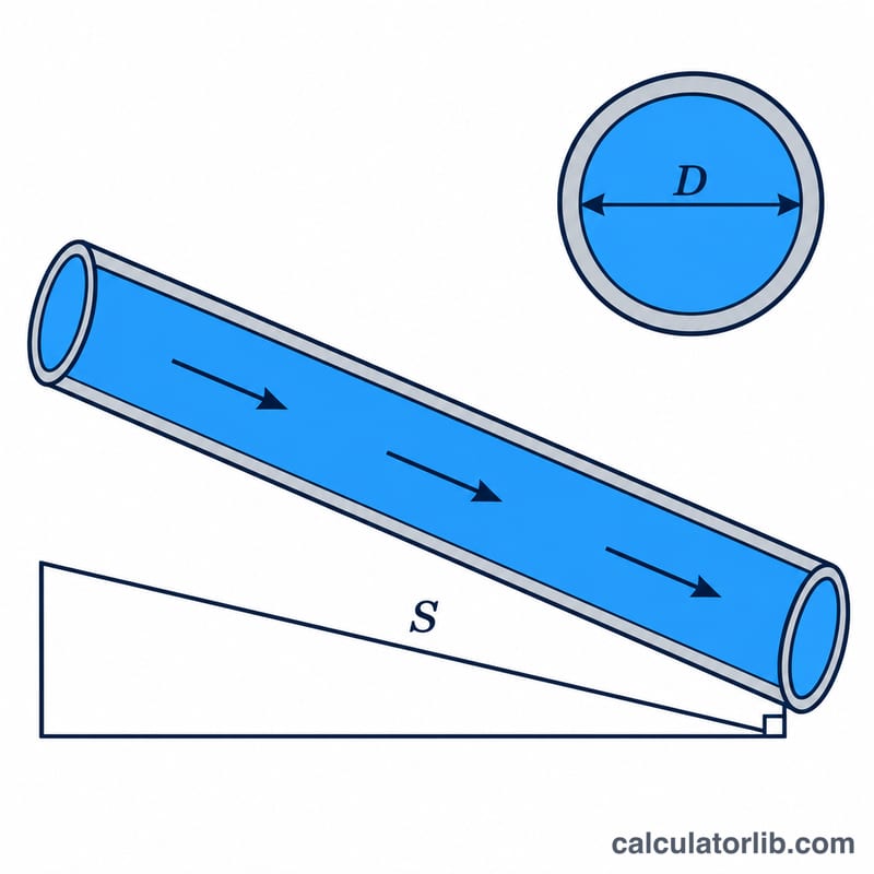
Enter the inside diameter in millimetres, the slope as a percentage (a 1% slope drops 1 m per 100 m of pipe), and the Manning roughness coefficient n. Smooth plastic pipe has n near 0.010, concrete about 0.013, and corrugated metal 0.024. The result shows flow in litres per second, cubic metres per second and US gallons per minute, plus velocity.
The formula explained
The calculation uses the Manning equation for open-channel and gravity flow:
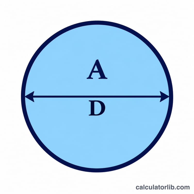
$$Q = \frac{1}{n} A R^{2/3} S^{1/2}$$Here \(Q\) is flow in m³/s, \(n\) is Manning roughness, \(A\) is the flow area in m², \(R\) is the hydraulic radius in m and \(S\) is slope in m/m. For a full circular pipe \(A = \pi D^2/4\) and \(R = D/4\). Velocity is \(V = Q/A\).
Worked example
A 300 mm concrete pipe (\(n = 0.013\)) laid at 1% slope: \(D = 0.3\) m, \(S = 0.01\).
$$A = \frac{\pi \times 0.3^2}{4} = 0.07069\,\text{m}^2, \quad R = 0.075\,\text{m}$$$$Q = \frac{1}{0.013} \times 0.07069 \times 0.075^{2/3} \times 0.01^{1/2} = 0.0967\,\text{m}^3/\text{s}$$That is about 96.7 L/s at a velocity of roughly 1.37 m/s.
Typical Manning Roughness Coefficients (n) by Pipe Material
Manning's n describes how much the pipe wall resists flow: a smoother wall has a lower n and carries more water at the same size and slope. The table lists typical design ranges for pipes flowing full.
| Pipe material | Typical n range | Common design value |
|---|---|---|
| PVC / HDPE (smooth wall) | 0.009 – 0.011 | 0.010 |
| Cast / ductile iron (cement-lined) | 0.012 – 0.013 | 0.013 |
| Concrete | 0.011 – 0.015 | 0.013 |
| Vitrified clay | 0.012 – 0.014 | 0.013 |
| Corrugated HDPE (smooth interior) | 0.012 – 0.020 | 0.012 – 0.015 (depends on manufacturer) |
| Corrugated metal | 0.022 – 0.026 | 0.024 |
These are typical design ranges only. Published values vary by source, manufacturer, pipe age, joint quality and the build-up of sediment or biofilm. Check the value your local standard or the manufacturer specifies.
Full-Flow Capacity by Diameter and Slope
The table shows full-pipe flow rate Q (L/s) and velocity V (m/s) for concrete with n = 0.013. Each value comes from the Manning equation with \(R = D/4\), \(A = \pi D^2/4\) and \(S\) as a fraction (1% = 0.01). Values are rounded.
| Diameter (mm) | Slope 0.5%: Q / V | Slope 1%: Q / V | Slope 2%: Q / V |
|---|---|---|---|
| 150 | 10.8 L/s / 0.61 m/s | 15.2 L/s / 0.86 m/s | 21.5 L/s / 1.22 m/s |
| 300 | 68.4 L/s / 0.97 m/s | 96.7 L/s / 1.37 m/s | 136.8 L/s / 1.93 m/s |
| 450 | 201.6 L/s / 1.27 m/s | 285.1 L/s / 1.79 m/s | 403.2 L/s / 2.54 m/s |
| 600 | 434.2 L/s / 1.54 m/s | 614.0 L/s / 2.17 m/s | 868.4 L/s / 3.07 m/s |
Sample substitution for D = 300 mm, S = 1%, n = 0.013: \(R = 0.075\) m, \(A = 0.07069\) m², \(V = \frac{1}{0.013}\,(0.075)^{2/3}\,\sqrt{0.01} \approx 76.92 \times 0.1778 \times 0.1 \approx 1.37\) m/s, so \(Q = 1.37 \times 0.07069 \approx 0.0967\) m³/s = 96.7 L/s.
Since \(Q \propto D^{8/3}\) and \(Q \propto S^{1/2}\), doubling the diameter raises capacity about 6.35 times (\(2^{8/3}\)). Doubling the slope raises it only about 1.41 times (\(\sqrt{2}\)). Going to a larger pipe is usually far more effective than steepening the slope.
Interpreting Your Result
The calculator gives the capacity of a circular pipe flowing completely full under gravity, with no pressure. Treat it as the upper limit, not the design flow.
- Minimum velocity: Gravity sewers and drains are commonly designed for a self-cleansing velocity of about 0.6–0.9 m/s so solids do not settle. The exact figure depends on the local code and the type of flow.
- Maximum velocity: Common upper limits are about 3–5 m/s, depending on the pipe material, to limit scour, abrasion and hydraulic shock. Plastic pipes often tolerate higher velocities than concrete or clay, but check the manufacturer's limits.
- Partial-depth design: Real pipes are usually designed to run at a partial depth, often 50–80% of the diameter, so there is spare capacity for surges, air space and future growth. At partial depth, velocity and flow differ from the full-pipe values and need a partial-flow calculation.
- Sensitivity to n: Capacity is inversely proportional to n. Using n = 0.015 instead of 0.013 reduces capacity by roughly 13%. Allow for ageing and sediment in the choice of n.
Local codes and standards set the roughness values, velocity limits, minimum diameters and slopes that apply to your project. This tool is for estimates; final designs should be checked by a qualified engineer.
FAQ
Does this work for partially full pipes?
No. It assumes the pipe flows full. A circular pipe flowing exactly half full carries half the full-flow rate and has the same velocity; other depths need partial-flow charts.
Is this the maximum capacity?
It is the full-pipe gravity capacity. Maximum discharge in a circular pipe actually occurs near 93% depth, only slightly above the full-pipe value.
What slope should I use?
Use the pipe invert drop divided by the pipe length, expressed as a percentage. Design codes usually require minimum velocities around 0.6 to 0.9 m/s to keep solids moving.