What this calculator does
A transformer is rated in kVA (kilovolt-amperes), the apparent power it can deliver continuously. This tool works in both directions: enter the line voltage and the load current to get the kVA a transformer must supply, or enter a kVA rating and voltage to get the full-load current that will flow at the terminals. It covers single-phase and three-phase systems and is based on pure electrical theory, so it applies anywhere in the world.
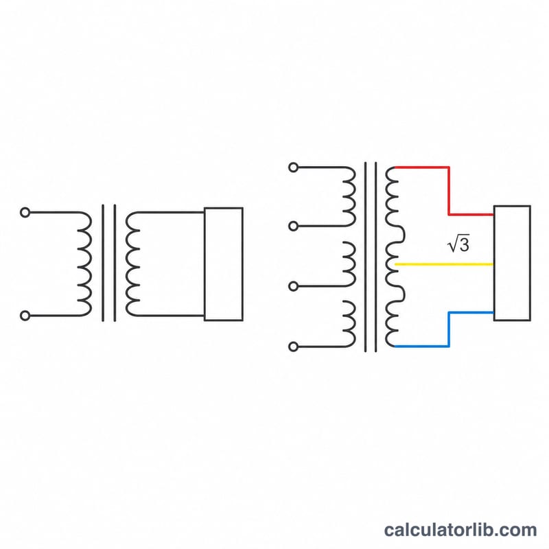
The formula explained
Apparent power is simply volts times amps, scaled to kilo units. For a three-phase system measured line-to-line, a factor of \(\sqrt{3}\) appears because the three phase currents are 120 degrees apart:
$$\text{kVA} = \frac{\sqrt{3} \times V \times I}{1000}$$where \(V\) = line-to-line voltage in volts and \(I\) = line current in amps. For single-phase drop the \(\sqrt{3}\) and use \(\text{kVA} = V \times I / 1000\). Rearranging gives the full-load current:
$$I = \frac{\text{kVA} \times 1000}{\sqrt{3} \times V}$$Real power follows from the power factor, \(\text{kW} = \text{kVA} \times \text{PF}\). Power factor never changes the kVA a transformer must carry, which is why transformers are rated in kVA rather than kW.
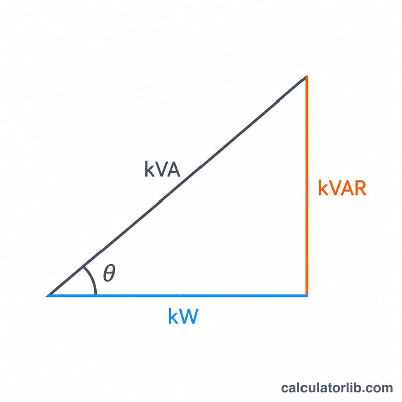
Worked example
A three-phase 480 V motor control centre draws 100 A at a power factor of 0.8:
$$\text{kVA} = \frac{1.7320508 \times 480 \times 100}{1000} = 83.14$$The real load is \(83.14 \times 0.8 = 66.51\) kW. The next standard rating above 83.14 kVA is 100 kVA, which also leaves roughly 20% headroom for future load.
Standard Transformer kVA Ratings and Full-Load Amps
Transformers are built in a ladder of preferred kVA sizes rather than arbitrary ratings, so a calculated load is normally rounded up to the next listed size. The table below gives the nameplate full-load line current for each standard rating at common secondary voltages. Single-phase currents use \(I = \dfrac{\text{kVA} \times 1000}{V}\); three-phase currents use \(I = \dfrac{\text{kVA} \times 1000}{\sqrt{3} \times V}\), where \(V\) is the line-to-line voltage.
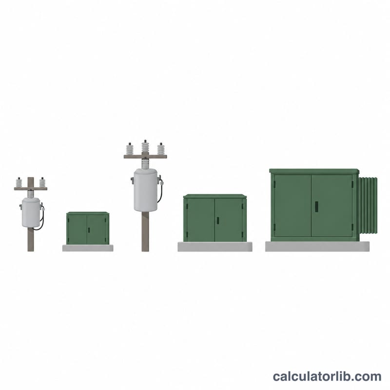
Note on voltages: 208 V, 240 V, 480 V and 600 V are North American distribution voltages, while 400 V three-phase (230 V line-to-neutral) is the common IEC/European low-voltage level. The 167 kVA and 37.5 kVA sizes are most often seen as single-phase pole-mounted or pad-mounted units in North America. All currents are rounded to the nearest whole amp and are nameplate full-load values only — they contain no growth allowance, no inrush allowance and no conductor or overcurrent-device derating. Local wiring rules (for example the NEC in the United States or IEC 60364-based national codes elsewhere) determine the actual cable and breaker sizes.
| kVA | Single-phase | Three-phase (line-to-line V) | |||||
|---|---|---|---|---|---|---|---|
| 240 V | 208 V | 208 V | 240 V | 400 V | 480 V | 600 V | |
| 3 | 13 | 14 | 8 | 7 | 4 | 4 | 3 |
| 5 | 21 | 24 | 14 | 12 | 7 | 6 | 5 |
| 7.5 | 31 | 36 | 21 | 18 | 11 | 9 | 7 |
| 10 | 42 | 48 | 28 | 24 | 14 | 12 | 10 |
| 15 | 63 | 72 | 42 | 36 | 22 | 18 | 14 |
| 25 | 104 | 120 | 69 | 60 | 36 | 30 | 24 |
| 37.5 | 156 | 180 | 104 | 90 | 54 | 45 | 36 |
| 50 | 208 | 240 | 139 | 120 | 72 | 60 | 48 |
| 75 | 313 | 361 | 208 | 180 | 108 | 90 | 72 |
| 100 | 417 | 481 | 278 | 241 | 144 | 120 | 96 |
| 150 | 625 | 721 | 416 | 361 | 217 | 180 | 144 |
| 167 | 696 | 803 | 464 | 402 | 241 | 201 | 161 |
| 225 | 938 | 1082 | 625 | 541 | 325 | 271 | 217 |
| 250 | 1042 | 1202 | 694 | 601 | 361 | 301 | 241 |
| 300 | 1250 | 1442 | 833 | 722 | 433 | 361 | 289 |
| 500 | 2083 | 2404 | 1388 | 1203 | 722 | 601 | 481 |
| 750 | 3125 | 3606 | 2082 | 1804 | 1083 | 902 | 722 |
| 1000 | 4167 | 4808 | 2776 | 2406 | 1443 | 1203 | 962 |
| 1500 | 6250 | 7212 | 4164 | 3608 | 2165 | 1804 | 1443 |
| 2000 | 8333 | 9615 | 5551 | 4811 | 2887 | 2406 | 1925 |
| 2500 | 10417 | 12019 | 6939 | 6014 | 3608 | 3007 | 2406 |
Reading the table: a 150 kVA three-phase transformer with a 480 V secondary delivers 180 A of line current at full nameplate load — the same transformer feeding a 208 V secondary would have to carry 416 A, which is why low-voltage secondaries drive much larger cable and busbar sizes for the same kVA.
How to Calculate Transformer kVA by Hand
- Decide single-phase or three-phase. The only difference between the two formulas is the \(\sqrt{3}\) factor. Single-phase: \(\text{kVA} = \dfrac{V \times I}{1000}\). Three-phase: \(\text{kVA} = \dfrac{\sqrt{3} \times V \times I}{1000}\). Using the wrong one introduces a 73% error.
- Confirm which voltage and current you have. For three-phase, \(V\) must be the line-to-line voltage (480 V, not 277 V; 400 V, not 230 V) and \(I\) must be the line current measured in a phase conductor. Both readings must also come from the same winding side — do not mix a primary voltage with a secondary current.
- Multiply voltage by current, then multiply by \(\sqrt{3} \approx 1.732\) if the system is three-phase. The result is in volt-amperes (VA).
- Divide by 1000 to convert VA to kVA. Example — a 480 V three-phase load drawing 120 A: $$\text{kVA} = \frac{1.732 \times 480\ \text{V} \times 120\ \text{A}}{1000} = \frac{99{,}766\ \text{VA}}{1000} = \mathbf{99.77}\ \text{kVA}$$ so the measured load is 99.77 kVA. At a power factor of 0.9 that is \(99.77 \times 0.9 = 89.79\) kW of real power, with \(\sqrt{99.77^2 - 89.79^2} = 43.5\) kVAR of reactive power.
- Add a margin for growth and inrush. A common design practice is 20–25% headroom, i.e. size the transformer so the calculated load sits near 75–80% of nameplate: \(99.77 \times 1.25 = 124.7\) kVA. This also keeps motor-starting and transformer energising inrush from pushing the unit into heavy overload, and leaves room for added load later. Treat 20–25% as a rule of thumb, not a code requirement — the actual minimum is set by the duty cycle, the harmonic content (K-factor) and your local wiring rules.
- Round up to the next standard rating. 124.7 kVA falls between the 112.5 and 150 kVA sizes, so the next standard unit up is 150 kVA. Never round down to a rating below the calculated load.
Reverse path: full-load amps from a kVA rating
To go the other way — nameplate kVA to full-load amps (FLA) — rearrange the same equation:
$$I_{3\phi} = \frac{\text{kVA} \times 1000}{\sqrt{3} \times V} \qquad I_{1\phi} = \frac{\text{kVA} \times 1000}{V}$$For the 150 kVA unit chosen above, with a 480 V three-phase secondary:
$$I = \frac{150 \times 1000}{1.732 \times 480} = \frac{150{,}000}{831.4} = 180.4\ \text{A}$$Primary / secondary current check
An ideal transformer transfers the same apparent power through both windings, so current scales inversely with voltage:
$$I_{\text{pri}} = I_{\text{sec}} \times \frac{ {V_{\text{sec}}}}{V_{\text{pri}}}$$With the 150 kVA transformer stepping 12,470 V down to 480 V, the primary full-load current is \(180.4 \times \frac{480}{12470} = 6.9\) A. Running the kVA formula on the primary side gives the same 150 kVA, which is the quickest sanity check that you have not mixed up winding sides or dropped the \(\sqrt{3}\). Real transformers have 1–3% losses, so measured primary kVA is slightly higher than secondary kVA.
Key Terms and Variables
| Term | Symbol / unit | Meaning |
|---|---|---|
| Apparent power | S — VA, kVA | The product of voltage and current, \(S = V \times I\) (times \(\sqrt{3}\) for three-phase). This is what a transformer is rated in, because its heating and its conductor size depend on current regardless of power factor. |
| Real power | P — W, kW | The power actually converted into work or heat by the load: \(P = S \times \text{PF}\). Motors, heaters and generator outputs are rated in kW. |
| Reactive power | Q — VAR, kVAR | Power that flows back and forth to magnetise motors and energise capacitance, doing no net work: \(Q = \sqrt{S^2 - P^2}\). It still produces current, so it still consumes transformer capacity. |
| Power factor | PF — unitless (0 to 1) | \(\text{PF} = P/S = \text{kW}/\text{kVA}\); the cosine of the phase angle between voltage and current for sinusoidal waveforms. A 0.8 PF load needs 25% more kVA than its kW figure suggests. |
| Line-to-line voltage | VLL — V | Voltage measured between any two phase conductors (e.g. 208, 400, 480, 600 V). This is the value used in the three-phase kVA formula. |
| Line-to-neutral voltage | VLN — V | Voltage between one phase and neutral. In a balanced wye system \(V_{LN} = V_{LL}/\sqrt{3}\): 120 V from 208 V, 230 V from 400 V, 277 V from 480 V. |
| Line current | IL — A | Current in a phase conductor feeding the transformer or load — what a clamp meter reads on an incoming cable, and the value used in the kVA formula. |
| Phase current | IPh — A | Current inside an individual winding. In a wye connection \(I_{Ph} = I_L\); in a delta connection \(I_{Ph} = I_L/\sqrt{3}\). |
| Full-load amps (FLA) | A | The current a winding carries at exactly its rated kVA and rated voltage. Also called rated current; it is a continuous-duty value, not a short-term limit. |
| Nameplate rating | kVA | The continuous apparent-power capacity the manufacturer guarantees at a stated voltage, frequency, ambient temperature and cooling class. Derating may apply at high altitude or high ambient temperature. |
| Turns ratio | a — unitless | \(a = N_1/N_2 = V_1/V_2 = I_2/I_1\). The ratio of primary to secondary winding turns, which sets the voltage transformation and the inverse current transformation. |
| Impedance | %Z — percent | The percentage of rated voltage needed to drive rated current into a short-circuited secondary. It governs voltage regulation under load and the available short-circuit current: lower %Z means stiffer voltage but higher fault current. |
| Delta connection | Δ | Three windings joined end-to-end in a closed loop, with no neutral point. Winding voltage equals line-to-line voltage; winding current is \(1/\sqrt{3}\) of line current. Commonly used on primaries and for three-wire motor loads. |
| Wye (star) connection | Y | Three windings joined at a common point that can be earthed and used as a neutral, giving both line-to-line and line-to-neutral voltages from one transformer — the usual arrangement for mixed lighting and power secondaries. |
| Phase factor | \(\sqrt{3} \approx 1.732\) | The constant that appears in three-phase power because the three line-to-neutral voltages are 120° apart. It converts between line and phase quantities and is the only term separating the single- and three-phase kVA formulas. |
FAQ
Why does three-phase use the square root of 3? With line-to-line voltage the per-phase voltage is \(V/\sqrt{3}\), and summing three phases gives \(3 \times V/\sqrt{3} = \sqrt{3} \times V\).
Should I size the transformer exactly at the calculated kVA? No. Engineers typically add 20 to 25% margin for load growth, motor inrush and harmonic heating, then round up to the next available rating.
Which voltage do I enter, primary or secondary? Either, as long as the current belongs to the same side. The kVA is the same on both sides; the current is not, because it scales inversely with voltage.