What is the Coaxial Cable Impedance Calculator?
This tool computes the characteristic impedance (Z₀) of a coaxial transmission line. Z₀ is the impedance a signal "sees" travelling along the cable, independent of its length. Matching source, line and load impedances (commonly 50 Ω or 75 Ω) minimises reflections, standing waves and signal loss in RF and video systems.
How to use it
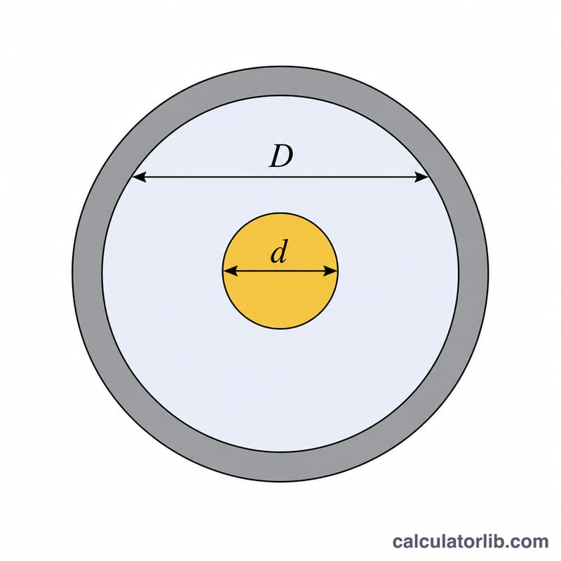
Enter three values: D, the inner diameter of the outer conductor (shield) in millimetres; d, the diameter of the inner conductor; and εr, the relative permittivity (dielectric constant) of the insulator between them. Air ≈ 1.0, solid PTFE ≈ 2.1, polyethylene ≈ 2.3. The units of D and d cancel, so any consistent length unit works.
The formula explained
The standard engineering approximation is Z₀ = (138 / √εr) · log₁₀(D/d). The √εr term in the denominator accounts for how the dielectric slows the wave and lowers impedance, while log₁₀(D/d) captures the geometry of the concentric conductors. Note this uses base-10 logarithm; the equivalent natural-log form uses the constant 60 instead of 138.
Worked example
For a cable with D = 7.25 mm, d = 2.0 mm and εr = 2.3: D/d = 3.625, log₁₀(3.625) = 0.55919, 138/√2.3 = 90.999, so Z₀ = 90.999 × 0.55919 ≈ 50.88 Ω — a typical 50-ohm coaxial line.
Dielectric Constants of Common Coaxial Insulators
The dielectric constant (relative permittivity, \(\varepsilon_r\)) of the insulating material between the inner and outer conductors directly scales the characteristic impedance: \(Z_0\) is proportional to \(1/\sqrt{\varepsilon_r}\). A lower \(\varepsilon_r\) (such as foamed or air-filled dielectric) raises impedance for the same geometry and also increases the velocity factor. The values below are typical ranges used in coaxial cable design.
| Dielectric Material | Relative Permittivity \(\varepsilon_r\) | Notes |
|---|---|---|
| Air (ideal/vacuum reference) | ~1.00 | Highest velocity factor; used in air-spaced lines |
| Foamed / cellular polyethylene (foam PE) | ~1.3 – 1.6 | Gas-injected PE; low loss, high velocity factor |
| Foam PTFE | ~1.4 – 1.7 | Low-loss microwave cable dielectric |
| FEP (fluorinated ethylene propylene) | ~2.1 | Plenum/high-temperature cable |
| PTFE / Teflon (solid) | ~2.05 – 2.1 | High temperature, low loss |
| Solid polyethylene (PE) | ~2.25 – 2.35 | Most common solid dielectric |
| Polypropylene | ~2.25 | Similar to solid PE |
Standard Coaxial Cable Types and Their Impedance
Coaxial cables are manufactured to standard nominal impedances — most commonly 50 \(\Omega\) for RF transmission and 75 \(\Omega\) for video and CATV distribution. The table lists widely used cable types with their nominal \(Z_0\), dielectric, and typical applications.
| Cable Type | Nominal \(Z_0\) | Dielectric | Typical Use |
|---|---|---|---|
| RG-58 | 50 \(\Omega\) | Solid PE | General RF, lab/test leads, thin Ethernet |
| RG-59 | 75 \(\Omega\) | Solid PE | Analog video, CCTV, baseband |
| RG-6 | 75 \(\Omega\) | Foam PE | CATV, satellite, broadband video |
| RG-8/U | 50 \(\Omega\) | Solid PE | Higher-power RF, amateur radio feedline |
| RG-174 | 50 \(\Omega\) | Solid PE | Miniature RF jumpers, instrumentation |
| RG-213 | 50 \(\Omega\) | Solid PE | Low-loss RF feedline, transmitters |
| LMR-400 | 50 \(\Omega\) | Foam PE | Low-loss antenna feedline, cellular/Wi-Fi |
FAQ
Why 50 Ω and 75 Ω? 50 Ω balances power handling and low loss for RF/test gear; 75 Ω minimises attenuation and is standard for video and cable TV.
Does length matter? No. Characteristic impedance depends only on geometry and dielectric, not cable length.
What dielectric constant should I use? Use the manufacturer's value; common values are air ~1.0, foamed PE ~1.5, solid PE ~2.3, PTFE ~2.1.