What is an LC Parallel Circuit Impedance Calculator?
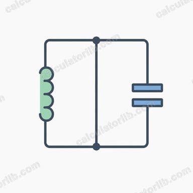
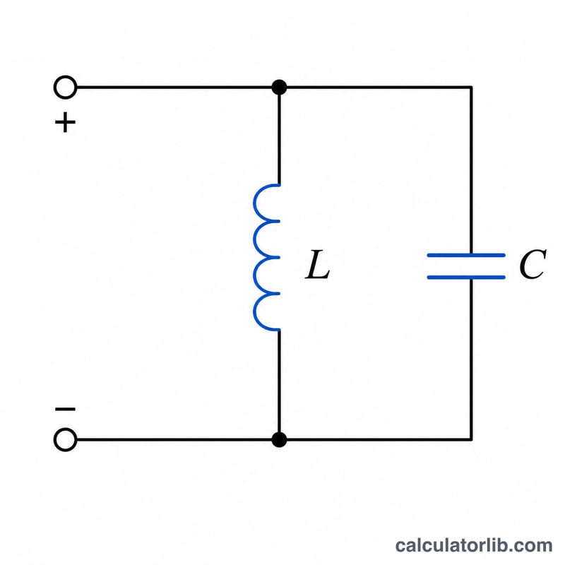
This tool computes the magnitude of impedance |Z| and the phase angle φ of an ideal (lossless) LC parallel circuit — an inductor L connected in parallel with a capacitor C — when driven at a frequency f. It is a universal physics/electronics tool and applies anywhere.
How to use it
Enter the inductance, capacitance and frequency, choosing the appropriate unit from each dropdown (mH, μH, μF, nF, kHz, MHz, etc.). The calculator converts every value to SI base units (henry, farad, hertz) before computing. The result shows |Z| in ohms, the phase φ in degrees, and the resonant frequency f0 for reference.
The formula explained
Angular frequency is \(\omega = 2\pi f\). For ideal parallel L and C the admittances add: \(1/Z = 1/(j\omega L) + j\omega C = j\cdot(\omega C - 1/(\omega L))\). The admittance is purely imaginary, so the magnitude is
$$|Z| = \dfrac{1}{\left|\dfrac{1}{\omega L} - \omega C\right|}$$The phase is +90° when \(1/(\omega L) > \omega C\) (net inductive), −90° when \(1/(\omega L) < \omega C\) (net capacitive), and 0° at resonance where the denominator is zero and \(|Z|\) is infinite (open circuit). Resonance occurs at
$$f_0 = \dfrac{1}{2\pi\sqrt{LC}}$$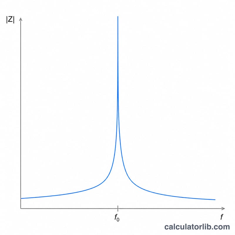
Worked example
\(L = 10\text{ mH} = 0.01\text{ H}\), \(C = 100\ \mu\text{F} = 1\text{E-}4\text{ F}\), \(f = 100\text{ Hz}\).
$$\omega = 2\pi\cdot100 = 628.3185\ \text{rad/s}$$$$\frac{1}{\omega L} = \frac{1}{628.3185\cdot0.01} = 0.159155\ \text{S}$$$$\omega C = 628.3185\cdot1\text{E-}4 = 0.0628319\ \text{S}$$$$\text{Denominator} = |0.159155 - 0.0628319| = 0.0963233\ \text{S}$$$$|Z| = \frac{1}{0.0963233} = 10.3817\ \Omega$$Since \(1/(\omega L) > \omega C\) the circuit is net inductive, so \(\varphi = +90°\).
FAQ
Why is the impedance infinite at resonance? At f0 the inductive and capacitive admittances cancel exactly, leaving zero net admittance, which means infinite parallel impedance — an ideal open circuit.
Why is the phase always ±90° or 0°? This is the lossless model with no resistance, so the net admittance is purely imaginary and the phase is exactly ±90°, or 0° at resonance.
What happens at DC (f = 0)? The ideal inductor becomes a short circuit, so \(|Z| \to 0\).