What this calculator does
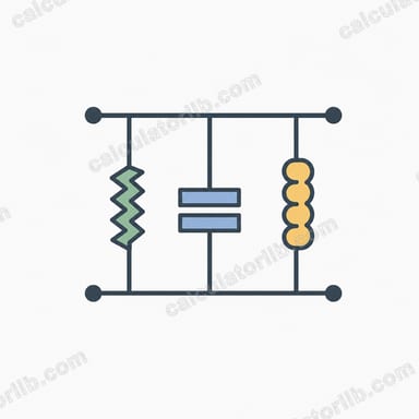
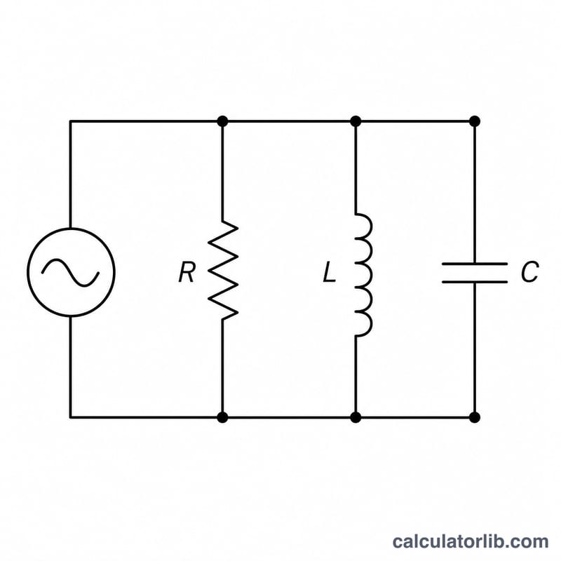
This tool computes the magnitude of the impedance, |Z|, for a resistor (R), capacitor (C) and inductor (L) connected in parallel and driven by a sinusoidal source at frequency f. Parallel RLC networks form the basis of tank circuits, filters and tuned amplifiers, where the impedance peaks sharply at resonance.
How to use it
Enter the resistance, capacitance, inductance and frequency, each with its own unit selector (e.g. μF, mH, kHz). The selected unit converts your value to SI base units before the calculation. The result is shown in kilohms (kΩ), again in base ohms (Ω), plus the phase angle of the impedance in degrees.
The formula explained
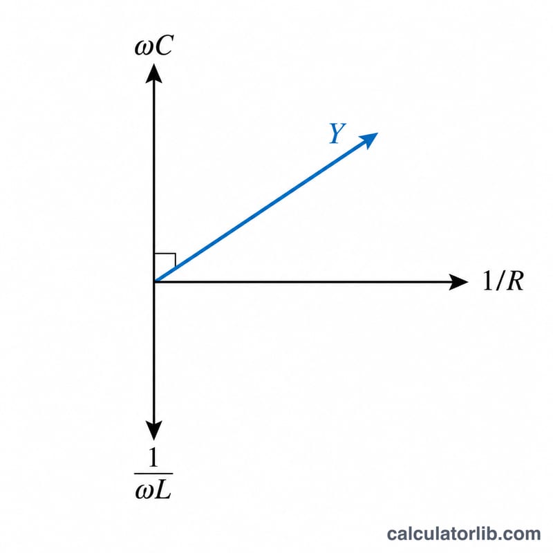
For parallel elements it is easiest to add admittances. With angular frequency \(\omega = 2\pi f\), the conductance is \(G = 1/R\), the capacitive susceptance is \(B_C = \omega C\), and the inductive susceptance is \(B_L = 1/(\omega L)\). The total admittance is \(Y = G + j(\omega C - 1/(\omega L))\), so its magnitude is $$|Y| = \sqrt{\left(\frac{1}{R}\right)^{2} + \left(\omega C - \frac{1}{\omega L}\right)^{2}}.$$ The impedance magnitude is simply the reciprocal, $$|Z| = \frac{1}{|Y|}.$$
Worked example
Take R = 10 Ω, C = 500 μF, L = 2 mH, f = 1 kHz. Then \(\omega = 2\pi \cdot 1000 = 6283.19\ \text{rad/s}\), \(\omega C = 3.14159\ \text{S}\), and \(1/(\omega L) = 0.079577\ \text{S}\). The imaginary part is 3.06202 S, and \(1/R = 0.1\ \text{S}\). So $$|Y| = \sqrt{0.01 + 9.37594} = 3.06365\ \text{S}$$ and \(|Z| = 1/|Y| \approx 0.32641\ \Omega\), i.e. about \(3.264 \times 10^{-4}\ \text{k}\Omega\). The phase is roughly −88.1°, so the network looks strongly capacitive at 1 kHz.
FAQ
When is |Z| largest? At resonance, where \(\omega C = 1/(\omega L)\) i.e. \(f = \frac{1}{2\pi\sqrt{LC}}\). The reactive terms cancel and |Z| equals R — the maximum for a parallel tank.
Why does |Z| go to zero at DC? An ideal inductor is a short circuit at zero frequency, so the parallel combination collapses to 0 Ω. The calculator returns 0 when f = 0, L = 0 or R = 0.
Why is the phase negative here? Above resonance the capacitive susceptance dominates, making the current lead the voltage, which gives a negative impedance phase.